Panasonic WVCW384 WVCW384 User Guide - Page 14
Video output connection, Make a connection, Caution
 |
UPC - 791871505830
View all Panasonic WVCW384 manuals
Add to My Manuals
Save this manual to your list of manuals |
Page 14 highlights
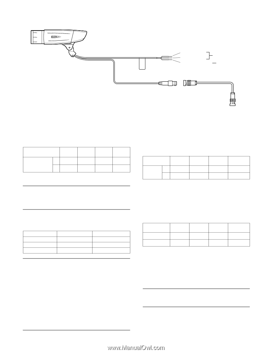
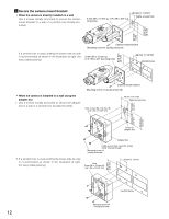
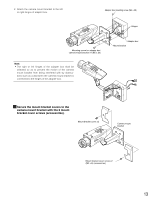
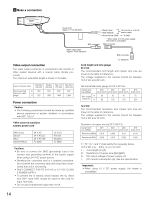
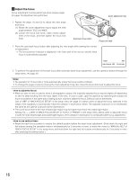
v Make a connection Power cord (Approx. 72 cm {28-3/8"}) BNC connector Brown (Live) Blue (Neutral) Green/Yellow (GND) To 24 V AC or 12 V DC power supply To GND * When using 12 V DC power supply, the heater is unavailable. BNC connector Video output cable (Approx. 72 cm {28-3/8"}) BNC connector To VIDEO IN Video output connection The video output connector is connected to the monitor or other system devices with a coaxial cable (locally procured). The maximum extensible length is shown in the table. Type of coaxial cable RG-59/U (3C-2V) Recommended m 250 maximum cable length ft 825 RG-6/U (5C-2V) 500 1 650 RG-11/U RG-15/U (7C-2V) (10C-2V) 600 800 1 980 2 640 Power connection Caution: • The following connections should be made by qualified service personnel or system installers in accordance with NEC 725-51. • Wire colors & functions Camera power cord Wire Color Brown Blue Green/Yellow 24 V AC 24 V AC (L) 24 V AC (N) To GND 12 V DC Positive Negative To GND Cautions: • Be sure to connect the GND (grounding) lead of the camera and grounding terminal of the power supply when using a 24 V AC power source. • Shrinking the cord-entry seal is a onetime procedure. Do not shrink the cord-entry seal until it has been ascertained that unit is functioning. • ONLY CONNECT THIS TO 24 V AC or 12 V DC CLASS 2 POWER SUPPLY. • To prevent fire or electric shock hazard, the UL listed wire VW-1 style 1007 should be used for the cord for Input Terminals. • Do not use a transformer larger than 10 VA. Cord length and wire gauge 24 V AC The recommended cord length and copper wire size are shown in the table for reference. The voltage supplied to the camera should be between 19.5 V AC and 28 V AC. Recommended wire gauge for 24 V AC line. Copper wire size (AWG) #24 #22 #20 (0.22 mm2) (0.33 mm2) (0.52 mm2) Wire length m 20 (Approx.) ft 66 30 45 100 150 #18 (0.83 mm2) 75 250 12 V DC The recommended resistance and copper wire size are shown in the table for reference. The voltage supplied to the camera should be between 10.5 V DC and 16 V DC. Resistance of copper wire [at 20 °C {68 °F}] Copper wire size (AWG) #24 #22 #20 (0.22 mm2) (0.33 mm2) (0.52 mm2) Resistance (Ω/m) 0.078 0.050 0.03 Resistance (Ω/ft) 0.024 0.015 0.009 #18 (0.83 mm2) 0.018 0.005 "L", "R", "VA ", and "I" shall satisfy the inequality below. 10.5 V DC ≤ VA - 2(R x I x L) ≤ 16 V DC L : Cord length (m) {ft} R : Resistance of copper wire (Ω/m){Ω/ft} VA : DC output voltage of power supply unit I : DC current consumption (A). See the specification. Important: • When using 12 V DC power supply, the heater is unavailable. 14
-
 1
1 -
2
-
3
-
4
-
5
-
6
-
7
-
8
-
 9
9 -
 10
10 -
 11
11 -
 12
12 -
 13
13 -
 14
14 -
 15
15 -
 16
16 -
 17
17 -
 18
18 -
 19
19 -
20
-
21
-
22
-
23
-
24
-
25
-
26
-
27
-
28
-
29
-
30
-
31
-
32
-
33
-
34
-
35
-
36
-
37
-
38
-
39
-
40
-
41
-
42
-
43
-
44
-
45
-
46
-
47
-
48
-
49
-
50
-
51
-
52
-
53
-
54
-
55
-
56
-
57
-
58
-
59
-
60
-
61
-
62
-
63
-
64
-
65
-
66
-
67
-
68
-
69
-
70
-
71
-
72
-
73
-
74
 |
 |