Sharp GX30 Service Manual
Sharp GX30 Manual
 |
View all Sharp GX30 manuals
Add to My Manuals
Save this manual to your list of manuals |
Sharp GX30 manual content summary:
- Sharp GX30 | Service Manual - Page 1
type, dispose of used batteries according to the instruction. CONTENTS SERVICING CONCERNS CHAPTER 1. GENERAL DESCRIPTION [1] Specifications 1-1 [2] Names of parts 1-2 [3] Operation manual 1-3 CHAPTER 2. ADJUSTMENTS, PERFORMANCE CHECK, AND FIRMWARE UPGRADE [1] SHARP Program Support Tool (SPST - Sharp GX30 | Service Manual - Page 2
GX30 PGSMESehEXarorvR3nki0eceVetICMIaNnuGalCONCERNS CONFIDENTIAL 1. When requested, back-up user's handset data using SPST (SHARP Program Support Tool). Otherwise, before servicing, warn the user that data in the memory may be lost during repairs. 2. Upgrade the firmware connection problems, do - Sharp GX30 | Service Manual - Page 3
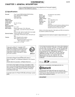
Infrared port 1.2 L/P (maximum distance 20 cm) Connector for AC charger and data cable Standard hands free connector (ø2.5) Battery running time depends on the battery and SIM card as well as the network conditions and usage Specifications for this model are subject to change without prior notice - Sharp GX30 | Service Manual - Page 4
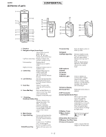
the mobile light is on, press this key to change the light colour. 23.Battery Cover 24.Macro Switch: (Close-up) Switches between normal ( ) and macro ( ) position. 25.Handsfree Kit Connector 26.Memory Card Slot Cover 27.External Connector: Used to connect either the charger or USB data cable - Sharp GX30 | Service Manual - Page 5
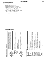
[3] Operation manual (Page numbers refer to the user guide) CONFIDENTIAL [Optional Accessories] Spare Lithium-ion battery (XN-1BT30) High capacity Lithium-ion battery (XN-1BT31) Cigarette lighter charger (XN-1CL30) USB data cable (USB cable: XN-1DC30) AC charger (XN-1QC30, XN-1QC31, XN-1QC32) - Sharp GX30 | Service Manual - Page 6
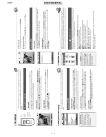
GX30 12 CONFIDENTIAL 1 - 4 New Messages Download Games News Sport - Sharp GX30 | Service Manual - Page 7
CONFIDENTIAL GX30 6-3-3 1-3 7-5 1 - 5 - Sharp GX30 | Service Manual - Page 8
GX30 - MEMO - CONFIDENTIAL 1 - 6 - Sharp GX30 | Service Manual - Page 9
you to adjust settings, conduct performance checks, and upgrade the firmware. [1] SHARP Program Support Tool (SPST) 1. System requirements • IBM PC compatible personal computer (standard COM1 115,200 bps serial port and USB required) Supported OS: Windows 98/98SE/2000/XP (except for Windows 95 - Sharp GX30 | Service Manual - Page 10
operable serial port of the PC with the supplied data cable. Make sure that the battery is fully charged. Start SPST from the desktop. 1. The Input password dialog box appears. Enter the password, select a port where GX30 is connected from the list box, and click "OK". If you do not know SPC - Sharp GX30 | Service Manual - Page 11
. Refer to the attachment 1 for the destination and operator name. GX30 Software version: A02-006-0184-GX30 Buttons Figure 4 Default Set User Data Back-up User Data Restore Downloader RF Calibration & Check RF Test User Password Reset Performance check adjustment **** mode release Exit Refer to - Sharp GX30 | Service Manual - Page 12
3. Adjustments for GX30 CONFIDENTIAL 1. Adjustments are required after replacing the following parts. ( ) Parts TH101 TH701 Main display unit External display unit Camera unit Temperature adjustment (Camera) Temperature adjustment (Battery) Main display flicker adjustment External display - Sharp GX30 | Service Manual - Page 13
default; and 3. Restores the values set by the user to default; CONFIDENTIAL (MEP_LOCK settings and the destination and the MEPLOCK data. Click "No" to restore default settings. 4) Communication starts. Figure 8 GX30 Figure 9 5) The following appears when you select "Yes" in step 3 and MEPLOCK - Sharp GX30 | Service Manual - Page 14
GX30 CONFIDENTIAL 6) After the handset is turned on, the initialization is complete. 4.2. User data back-up SPST saves all the data stored on the handset. Figure 11 1. Set the COM port on the SPST initial screen and click "User Data Back-up". 2. Specify the file name in the following dialog box - Sharp GX30 | Service Manual - Page 15
the backed up data. CONFIDENTIAL 1. Set the COM port on the SPST initial screen and click "User Data Restore". 2. Specify the file name in the following dialog box and click "Save". GX30 3. The communicating dialog box appears while processing. Figure 15 4. When the restore is complete, click - Sharp GX30 | Service Manual - Page 16
1. Connect the cable to a PC. 2. Connect the cable to handset. 3. The photo below shows handset connected to a PC. Figure 18 Figure 19 B) Using Communication Box 1. Connect a PC to Communication Box via a serial cable. 2. Connect the AC charger to Communication Box and then plug it into the outlet - Sharp GX30 | Service Manual - Page 17
occur and the MOT file rewrite operation may fail. Make sure the handset battery is sufficiently charged. If the battery is low, the MOT file rewrite operation may fail. Charge the battery before the operation. Disconnect the AC charger from a cable for upgrading. When rewriting MOT files using the - Sharp GX30 | Service Manual - Page 18
4.4.2 Rewriting MOT files This section describes how to rewrite MOT files using the upgrading tool. 1) Activating Software 1. Double click the shortcut icon on your desktop or click "The GX30 Upgrading Tool" on the Start menu. 2. The upgrading tool is activated. Figure 24 Figure 25 [Note - Sharp GX30 | Service Manual - Page 19
CONFIDENTIAL GX30 2) Selecting options and COM port 1. Uncheck the check box when using a cable for upgrading. Leave it checked when using Communication Box. 2. To initialize user area, check the File System Initialize check box. (User data will be deleted and the handset status will return to - Sharp GX30 | Service Manual - Page 20
GX30 CONFIDENTIAL You can shorten time for the MOT file rewrite operation ] When you check File System Initialize check box and click the "OK" button, handset status returns to the default. In this case, user data is initialized after the MOT file rewrite operation. Uncheck the check box to avoid - Sharp GX30 | Service Manual - Page 21
3) Selecting a MOT file 1. Click the "Select File" button. The Open dialog box appears. CONFIDENTIAL GX30 Figure 31 [Open dialog box] 2. Click the " " button to open a desired folder. 3. A Motorola file (.mot) in the folder appears. Click a file to write in. 4. Click - Sharp GX30 | Service Manual - Page 22
GX30 4) Rewriting a MOT file Click the "Start Loading Flash" button to start rewriting. CONFIDENTIAL Figure 34 1. "Press Power Button" appears. Hold down the Power key. Turn on handsets from No.10 down to No.1 (turn on only the - Sharp GX30 | Service Manual - Page 23
handsets turned on. GX30 Figure 37 4. When the rewrite operation starts, handset display screen shows the software version charger from the cable. Otherwise charging starts and the MOT file rewrite operation is interrupted. 2. Make sure the handset battery is sufficiently charged. If the battery - Sharp GX30 | Service Manual - Page 24
GX30 CONFIDENTIAL 5) Checking the value of SUM When the rewrite operation is completed, a confirmation message appears with SUM. SUM also appears on handset. - Sharp GX30 | Service Manual - Page 25
Communication Box, turn off SET POWER SW and then disconnect the cable from handset. 7) Initializing only the file system Follow the instructions below to initialize only the file system. (User data will be deleted and the handset status will return to the default.) * Perform this procedure when the - Sharp GX30 | Service Manual - Page 26
10 ADR = XXXXXXXX 11 STR =XX Descriptions/Instructions An error in Flash Rom. Start over the rewrite operation. The upgrading tool is damaged. Uninstall and reinstall the upgrading tool, and start over the rewrite operation. Flash Rom is protected. Battery may be too low. Use a sufficiently - Sharp GX30 | Service Manual - Page 27
RF calibration & check CONFIDENTIAL Stabilized power supply Handset RF cable GSM tester GX30 Test battery Data cable PC Figure 43 4.5.1 Preparation • Connect PC and GSM tester with a GPIB cable. • Connect PC and handset with a Data cable. (Use a test battery or one close.) • Connect a RF cable - Sharp GX30 | Service Manual - Page 28
GX30 4.5.2 Default setting for the program. • Activate the program and set defaults. CONFIDENTIAL 1) Select the COM port. 2) Set the GPIB No. 3) Select the test instrument. 4) Set - Sharp GX30 | Service Manual - Page 29
GX30 Figure 45 4. Apply 4 V using a stabilized power supply and turn on the handset. After the handset enters handset is on and click "OK". (Adjustment starts.) Figure 46 6. Click "OK". Figure 47 7. The initial screen returns. Figure 48 The following appears when the handset software - Sharp GX30 | Service Manual - Page 30
GX30 CONFIDENTIAL 4.5.4 RF performance check 1. Apply 4 V using a stabilized power supply and turn on the handset. 2. Start "RF calibration & on the handset. After the handset enters Standby mode, lower the voltage to 3.7 V, enter the PIN code and click "OK". 5. Make sure the handset is in the - Sharp GX30 | Service Manual - Page 31
The following will be displayed in case of failure. See the attachment 2 for troubleshooting. CONFIDENTIAL GX30 7. Click "OK". 8. The initial screen returns. Figure 54 Figure 55 2 - 23 - Sharp GX30 | Service Manual - Page 32
GX30 Attachment 2 Whole inspection list by RF performance check. Band Send- No. Item to be inspected ing/ Recei ve GSM Tx 1 Burst Power 900 2 Burst Power 3 - Sharp GX30 | Service Manual - Page 33
Error (Peak) 241 Phase Error (Peak) 242 Phase Error (Peak) 243 Mod_spectrum -800 244 Mod_spectrum -600 245 Mod_spectrum -400 246 Mod_spectrum -250 GX30 Channel PCL 699CH 699CH 512CH 512CH 512CH 512CH 512CH 512CH 512CH 512CH 885CH 885CH 885CH 885CH 885CH 885CH 885CH 885CH 699CH 699CH 699CH - Sharp GX30 | Service Manual - Page 34
GX30 Band Send- No. Item to be inspected ing/ Recei ve 247 Mod_spectrum -200 248 Mod_spectrum +200 249 Mod_spectrum +250 250 Mod_spectrum +400 251 Mod_spectrum +600 - Sharp GX30 | Service Manual - Page 35
454 Rx Sensitivity 455 Usable Receiver Level 456 Rx Level Reports GX30 Channel PCL 128CH 128CH 128CH 128CH 128CH 128CH 128CH 251CH 251CH FL803, FL902, FL904, FL905 IC801 IC801, FL803, FL902, FL904, FL905 Troubleshooting list Check parts for DCS IC802, FL803, FL905 TCX801 IC801 IC801, TCX801 - Sharp GX30 | Service Manual - Page 36
test tool CONFIDENTIAL 4.6.1 Requirements For repairs, this test checks the condition of an electric board (especially the RF section). • PC with COM port • GX30 Data Cable • PWB repair jig • GSM Tester (CMU200) 4.6.2 Setup 1. Set PWB and make connections as shown in Figures 56 and 57. Make sure - Sharp GX30 | Service Manual - Page 37
CONFIDENTIAL Black Red GSM Tester (CMU 200) PC GX30 PWB repair jig Figure 57 Connections Data Cable Points Figure 58 Contact points 2 - 29 - Sharp GX30 | Service Manual - Page 38
GX30 CONFIDENTIAL 2. Apply 4 V using a stabilized power supply and turn on the handset. Push Figure 59 Turning power on 3. Start RF test tool. 4. Select a COM port to which Data Cable is connected. (Figure 60) 5. Press the "Initialize & Read - Sharp GX30 | Service Manual - Page 39
CONFIDENTIAL 4.6.3 Tests 1) BAND Select & Channel Select a band and a channel to test. Settings are applied to all tests. Band selection GX30 Input box [Procedure] 1. Select a band. (GSM850, GSM900, DCS or PCS) 2. Select or enter a channel using Channel bar or Input box. Figure 62 Channel bar - Sharp GX30 | Service Manual - Page 40
GX30 GX30 TX power Table (25°C, voltage: 3.7[V]) GSM850 Band PCL GSM850 +/-3 dB +/-3 dB +/-3 dB +/-3 dB +/-3 dB +/-3 dB +/-5 dB +/-5 dB +/-5 dB +/-5 dB 3) RX test The handset receives burst signals in this test. CONFIDENTIAL GSM900 Band PCL GSM900 [dBm] 5 33 6 31 7 29 8 27 9 25 - Sharp GX30 | Service Manual - Page 41
aerial connector. GX30 Estimated Power Input box (Integer only) Measured power box Measure button Figure 65 [Procedure] 1. Connect the handset and GSM less than 3dB. 4.6.4 Termination Turn off the handset to ensure proper operations. 4.6.5 Trouble imfomation When switching DCS and PCS, change - Sharp GX30 | Service Manual - Page 42
GX30 CONFIDENTIAL 4.7. Password reset SPST resets the password (handset code is set to "0000"). 1) Set the COM port on the SPST initial screen and click "User Password Reset". Click "Yes" to reset. Click "No" to exit. 2) When completed, the following appears. Figure 66 Figure 67 - Sharp GX30 | Service Manual - Page 43
4.8. Performance check and adjustment With this function, SPST checks the performance of the handset and makes adjustments. GX30 1) Set the COM port on the SPST initial screen and click " "OK". • If a failure occurs, see "10. Back Light does not turn on." in [3] Troubleshooting. 2 - 35 - Sharp GX30 | Service Manual - Page 44
Troubleshooting. 4.8.5 Battery voltage check Click to display the current battery voltage. • If a failure occurs, see "1. Power is not turned on." in [3] Troubleshooting is not recognized." in [3] Troubleshooting. 4.8.7 Vibrator test Click to vibrate the handset. Click "OK" to exit. • If a - Sharp GX30 | Service Manual - Page 45
Hands free receiver (4) Hands free microphone Handset receiver (3) & (4): No voice is heard. (3): Voice is heard. (4): No voice is heard. (3): No voice is heard. (4): Voice is heard. Troubleshooting (based on [3] Troubleshooting) See "Phone" in the section "2. Voice transmission/recording - Sharp GX30 | Service Manual - Page 46
GX30 CONFIDENTIAL 4.8.12 LCD test Check that the specified color appears on the main display. • If a failure occurs, see "12. The display does not appear on Main Display." and "13. The display does not appear on External Display (in 65K color mode)." in [3] Troubleshooting. 4.8.13 Temperature - Sharp GX30 | Service Manual - Page 47
contrast adjustment Click the "External display contrast adjustment" button. The following screen appears. GX30 DEN: 075 8-level gradation pattern (black & white pattern) Figure 76 Comparing with an adjusted handset, click " " or " " to adjust the value so that the same gradation pattern is - Sharp GX30 | Service Manual - Page 48
GX30 CONFIDENTIAL When an error occurs, the corresponding message appears. Solve the problem according to "Solution". • Error 1 Error message: "There are too many white cracks correction sheet as shown in Figure 80. Attach the sheet to the handset firmly with clear scotch tape. Figure 80 2 - 40 - Sharp GX30 | Service Manual - Page 49
by using an illuminance meter. In the proper position for black defect correction, illuminance is between 8,000 and 10,000 lux. GX30 3. Hold the handset in the proper position. Figure 81 4. Click the "Black defect correction" button. The following message is displayed. Figure 82 5. Click the - Sharp GX30 | Service Manual - Page 50
GX30 6. The result is displayed within a minute as follows. CONFIDENTIAL Figure 85 When an error occurs, the corresponding message appears. Solve the problem . Solution: Replace the camera unit. 4.9. ****mode release When the handset does not turn on and enter the normal mode, use this function - Sharp GX30 | Service Manual - Page 51
) is possible using a Bluetooth headset. GX30 Recommended Bluetooth headset: JABRA BT200 PLANTRONICS M1000 PLANTRONICS M3000 5.2. USB Connect GX30 and a PC with a USB cable. Check that GX30 is recognized as a device. If the USB driver for GX30 (SHARP GSM GPRS USB Driver) is not installed on - Sharp GX30 | Service Manual - Page 52
GX30 [2] Test points MAIN PWB-A (FRONT SIDE) CONFIDENTIAL TP705 TP720 TP729 TP730 TP709 TP710 TP711 TP737 TP731 TP721 TP734 TP723 TP724 TP714 TP712 TP717 TP713 TP736 - Sharp GX30 | Service Manual - Page 53
MAIN PWB-A (REAR SIDE) CONFIDENTIAL TP708 TP718 TP704 TP703 GX30 TP719 TP No. TP703 SP1 Signal name Figure 90 TEST POINT TP No. TP704 SP2 Signal name 2 - 45 - Sharp GX30 | Service Manual - Page 54
TP180 TP127 TP126 TP182 TP183 TP514 TP113 TP502 TP503 GX30 KEY PWB-B (FRONT SIDE) CONFIDENTIAL TP121 TP163 TP162 insert check terminal 4 VBAT VBAT BATT_SENSE BT_VCC (3.0V) VBUS_IN POWONKEY USB D+ USB D- RTS CTS DGND DGND Reserved ManufactUre Specific CHGIN VTCXO (2.9V) VRF (2.9V) 2 - 46 - Sharp GX30 | Service Manual - Page 55
KEY PWB-B (REAR SIDE) CONFIDENTIAL GX30 TP128 TP132 TP145 TP148 TP143 TP138 TP137 TP533 TP530 TP529 TP516 TP518 TP501 TP520 TP522 TP504 TP133 TP131 TP117 TP110 TP106 TP517 TP519 TP130 TP134 - Sharp GX30 | Service Manual - Page 56
GX30 [3] Troubleshooting CONFIDENTIAL 1. Power is not turned on. 2. Voice transmission/recording is impossible. 3. No voice is heard from the earpiece. 4. Battery does not charge. 5. Vibrator does not work. 6. Clock Settings are reset. 7. Speaker does not work. 8. MP3 cannot be played. 9. Video/ - Sharp GX30 | Service Manual - Page 57
(From page 2-48) A CONFIDENTIAL GX30 Is 3.6 V or more applied to BATT terminal (TP520)? YES YES IC801 and peripheral circuits are defective. NO Battery terminals are defective, connector terminal is dirty, or soldering is improper. NO The battery is defective or set improperly. NO Fuse ( - Sharp GX30 | Service Manual - Page 58
GX30 CONFIDENTIAL 2. Voice transmission/recording is impossible. Phone (Handset) Replace the microphone. Is the problem solved? NO Is applied to R192 (IC106 pin 89 side)? YES Replace C126 or C133. Is the problem solved? NO IC103 and IC106 are defective. IC103 is defective. NO Is approx. 1.7 - Sharp GX30 | Service Manual - Page 59
CONFIDENTIAL GX30 Hands problem solved? NO IC103 and IC106 are defective. IC103 is defective. NO Is approx. 1.7 V applied to IC103 pin 95? NO YES R262 and R129 are defective. IC103 is defective. NO Jack JK101 is defective, or the jack plug is in a poor contact with hands free kit (Handset - Sharp GX30 | Service Manual - Page 60
GX30 3. No voice is heard from the earpiece. CONFIDENTIAL Phone (Handset) Is the signal sent to the contact terminal of the earpiece? NO Is the signal sent Jack JK101 is defective, or the jack plug is in a poor contact with hands free kit. (Handset mode is set.) NO IC103 is defective. 2 - 52 - Sharp GX30 | Service Manual - Page 61
) - Option Is the stereo headset the one specified by Sharp? YES CONFIDENTIAL GX30 The headset cannot be used. (It works as a monaural defective, or the jack plug is in a poor contact with hands free kit. (Handset mode is set.) NO IC103 is defective. YES Jack JK101 is defective, or the - Sharp GX30 | Service Manual - Page 62
GX30 4. Battery does not charge. CONFIDENTIAL Set a battery of 3.8 - 3.9 V and connect the charger. YES Is the mobile light turned on red? YES Set a battery the mobile light is defective. * For settings and connections for SPST, refer to the "ADJUSTMENTS, PERFORMANCE CHECK, AND FIRMWARE UPGRADE" - Sharp GX30 | Service Manual - Page 63
GX30 Is 2.5 V or more applied to TP168 with a battery in the handset? YES Is 1.5 V or more applied to TP167 without a battery in the handset? YES X101, R169, R174A, and C176 are defective. The holder is installed improperly. NO NO Is back-up battery sound of Video and MP3 can be heard by - Sharp GX30 | Service Manual - Page 64
GX30 8. MP3 cannot be played. Speaker Is Ringer Volume set to "Silent"? NO CONFIDENTIAL Not defective. YES YES Cancel "Silent". Is sound produced? NO Is output of the video and voice recorder normal? YES Insert an SD card with MP3 files recorded on a normal unit. Do they play? NO Is the SD - Sharp GX30 | Service Manual - Page 65
CONFIDENTIAL 9. Video/Voice Recorder playback is impossible. GX30 Speaker Are keypad tones and ring tones normal? YES In Playback window, does playback start normally and the capacity bar change? YES Is Ringer Volume - Sharp GX30 | Service Manual - Page 66
GX30 10. Back Light does not turn on. CONFIDENTIAL Is VBAT voltage applied to YES IC707, and R707 are defective. Go to the setting as follows and set it to On: NO Settings → Phone settings Main display → Back light NO Does it turn on? YES Not defective. NO CN705 is defective. Back light - Sharp GX30 | Service Manual - Page 67
? NO FL905 or J801 is defective. IC801 is defective. YES FL904 is defective. YES FL901, FL902, or FL903 is defective. YES YES FL803 is defective. GX30 2 - 59 - Sharp GX30 | Service Manual - Page 68
GX30 CONFIDENTIAL 12. The display does not appear on Main Display. Is Main Display unit fully inserted to CN704? YES Clean the contact point of CN704 - Sharp GX30 | Service Manual - Page 69
does not appear on External Display (in 65K color mode). GX30 Does the display appear on Main Display? NO Go to the to On? Go to the setting as follows and set it to On: NO Settings → Phone settings External display → Display On/Off YES Is External Display unit fully inserted to CN703? NO - Sharp GX30 | Service Manual - Page 70
GX30 14. Pictures cannot be taken. CONFIDENTIAL Replace camera relay FPC. Does camera work? NO Is 2.5 V applied to TP705? YES Is 2.5 V applied to pin 23 of - Sharp GX30 | Service Manual - Page 71
relay FPC is broken. GX30 Is -8 V applied to for SPST, refer to "ADJUSTMENTS, PERFORMANCE CHECK, AND FIRMWARE UPGRADE" (see page 2-1). The control line between IC707 or all three colors YES Replace with a battery of 3.8 - 3.9 V, and connect the charger to the external connector. Does the flash - Sharp GX30 | Service Manual - Page 72
GX30 16. SIM card is not recognized. CONFIDENTIAL Replace the SIM card. Is it recognized? NO YES SIM card is defective or not the one specified. - Sharp GX30 | Service Manual - Page 73
CONFIDENTIAL 17. SD (Memory) card is not recognized. GX30 Is the SD card checked for operation? YES Is the SD card recognized on PC, etc.? YES Is the card insertion detected? YES Is 2.75 V - Sharp GX30 | Service Manual - Page 74
GX30 CONFIDENTIAL 18. IrDA (Infrared) communication is not possible. Set the distance and angle within the specification for the IrDA communication. Is 2.8 V supplied from Q104 pin 2? YES Is 2.8 V applied to UN101 pin 6? YES Does the send signal (UN101 pin 5) send pulse waves - Sharp GX30 | Service Manual - Page 75
IC505 is defective. NO IC106 is defective. NO IC506 is defective. NO IC106 is defective. Handset can be connected to Bluetooth headset, but sound is not heard. YES Is waveform of PCMCLK signal (approx. 256 kHz IC106 is defective. NO IC506 is defective. NO IC106 is defective. GX30 2 - 67 - Sharp GX30 | Service Manual - Page 76
that is not recognized. Is it recognized? YES Is a communication with the handset established via SPST for GX30? YES Connect to a Data with the USB cable. NO Reinstall the driver and replace the USB cable to connect the handset. NO IC106, IC502, and IC504 are defective. Is TP536 at "H"? YES Is - Sharp GX30 | Service Manual - Page 77
GX30 [1] Servicing that you can open and close handset smoothly and hear tick sound of make sure that all three battery terminals protrude evenly. 5. Please electric screwdriver (HIOS CL4000) is used. • SOLDERING SPECIFICATION Soldering iron must be set to 350° C for Driver [Magnet/Cushion, Driver] - Sharp GX30 | Service Manual - Page 78
GX30 CONFIDENTIAL Camera Relay FPC PWB-F Standard position Standard position Cushion, Connector Key A-A [Sheet, Hinge Cover] Standard position Cushion, Battery Standard position Standard position Section A-A [Cushion, Battery] External Display Standard position Standard position 3 - 2 - Sharp GX30 | Service Manual - Page 79
BB Standard position Standard position CONFIDENTIAL Insulator, BB A GX30 Standard position Standard position Spacer, Infrared Port B Section B-B Be careful to avoid contact of AN501 (Bluetooth aerial) with the Camera Ground FPC. Bluetooth aerial Standard position Camera Ground FPC PWB-D - Sharp GX30 | Service Manual - Page 80
GX30 [2] Disassembly and reassembly CONFIDENTIAL • To reassemble, follow the reverse procedure. STEP REMOVAL 1 Back Cabinet (Key) Ass'y PROCEDURE 1.Battery Cover........ (A1)x1 2.Li-Ion Battery the cover downward. Remove the SD cover belt as instructed below. SD Card Cover (A1) x 1 1 SD - Sharp GX30 | Service Manual - Page 81
/SIM FPC 1.Hook E1)x1 6 PWB-G 2.Hook E2)x2 6 BB Shield Plate 1.Hook F1)x1 7 GX30 SD/SIM FPC PWB-G/ BB Shield Case (D3) x 1 (D2) x 1 (D3) x 2 Key insert a small flat head screwdriver and lever it up as illustrated. Hook Minus Driver Figure 5 BB Shield Case SD/SIM FPC PWB-G (E2) x 2 ( - Sharp GX30 | Service Manual - Page 82
GX30 CONFIDENTIAL STEP REMOVAL 7 Back Cabinet (Display) PROCEDURE Open the handset 1.Screw Cover.......... (G1)x3 2.Screw G2)x4 Close the handset 3.Hook G3)x4 4.Hook G4)x1 FIGURE 8 9 8 Main PWB-A Open the handset and lever it up as illustrated. Hook Minus Driver Figure 10 3 - 6 - Sharp GX30 | Service Manual - Page 83
Side Frame J1)x1 12 (Key)/ 2.Hinge J2)x2 Front Cabinet (Display) (I3) x 3 (I4) x 3 GX30 External Display/ External Display Holder Assembly Main PWB-A (I2) x 2 (I2) x 1 (I1) x 1 Minus Driver Main Display (I3) x 4 Main Display/ Main Display Holder Assembly Be careful dirt and dust do not - Sharp GX30 | Service Manual - Page 84
GX30 PGSMECehXaHrorv3nkAi0eceetPMTaEnuRal4. DIAGRAMS [1] Block diagram SECTION POWER ON RESET GENERATOR REGULATOR CONTOROL BATTERY CHARGER ASFS ASDI ASDO VINT IC108 nRESET R3112Q261A USB DUSC[2](TxD) USC[5](CTS/Genie_Tx) USC[0](Genie_Tx) 6 3 7 USC[4](RTS/Genie_Rx) USC[1](RxD) USB - Sharp GX30 | Service Manual - Page 85
GX30 DISPLAY RTC KEYPAD BMC SIM USC UART USB 1.1 Fast IrDA I2C Back light SPI( PCM_DATAOUT) IC506 UGNZ2 BLUETOOTH MODULE RESET GTDIO_B(RESET (CINT) VDD2 EXCKI V-DRIVER MODE IC701 R116025B REG GPO_23(Sleep Control for PSRAM2) VBAT Li-ION BATTERY 780mAh SRAM 4Mbit(x 16) nGPCS2 VBACK P-SRAM - Sharp GX30 | Service Manual - Page 86
GX30 CONFIDENTIAL [RF] BS1 (D) BS2 (D) BS3 (D) BS4 (D) PA (A) VBAT 2 6 1,3 Power TCXOEN (D) Supply 4 IC804 R5322N002B 5 IP (A) IN (A) QP (A) QN (A) VRF VTCXO TP802 TP801 23 24 25 26 - Sharp GX30 | Service Manual - Page 87
CONFIDENTIAL GX30 BS2 BS3 1,2 4 IC805 5 NL17SZ32XV5T2 LOGIC Tx VCO LOOP GSM850 824.2 to 848.8 MHz VBAT BS2 FILTER 12 GSM900 880.2 to 914.8 MHz DCS1800 1710.2 to - Sharp GX30 | Service Manual - Page 88
GX30 CONFIDENTIAL PGSMECehXaHrorv3nkAi0eceetPMTaEnuRal5. SCHEMATIC DIAGRAM AND WIRING SIDE OF P.W.BOARD [1] Notes on schematic diagram • Resistor: To differentiate the units of resistors, the symbols K and M are used. - Sharp GX30 | Service Manual - Page 89
) RF Test Tool Rx test GSM850 Band 8 BS1 C870 (FL803 10Pin) 9 BS2 C871 (FL803 6Pin) 10 BS3 C872 (FL803 12Pin) 11 BS4 C874 (FL803 14Pin) 5 - 2 GX30 - Sharp GX30 | Service Manual - Page 90
GX30 RF Test Tool Rx test GSM900, DCS1800 Band 8 BS1 C870 (FL803 10Pin) 9 BS2 C871 (FL803 6Pin) 10 BS3 C872 (FL803 12Pin) 11 BS4 C874 (FL803 - Sharp GX30 | Service Manual - Page 91
16 VSYNC (Stand-by) C760 CONFIDENTIAL 17 SUBFLM (Stand-by) L711 1Pin 18 TCXOEN (Stand-by) IC804 1Pin GX30 5 - 4 - Sharp GX30 | Service Manual - Page 92
GX30 CONFIDENTIAL [4] Schematic diagram/Wiring side of P.W.Board MAIN PWB-A A CAMERA GROUND FPC PWB-D Battery VBAT TO KEY DATA[6] DATA[7] DATA[12] LCDRSP 16 D13 15 LCD_RSP DATA[13] H BTRESET 14 D14 13 USB C CNT DATA[14] NOTES ON SCHEMATIC DIAGRAM can be found on page 5-1. 1 2 3 - Sharp GX30 | Service Manual - Page 93
CONFIDENTIAL GX30 IC701 R116025B 2.5V REGULATOR 1 Vdd Vout 5 2 GND 3 CE ECO 4 2.2 R705 0 TP705 R720 C709 1 R712 0 G 5-11 (5-F) CAM_3V_CTL C718 0.1 1 Cont Vin 5 2 GND 3 Np(Vref) Vout 4 C721 0.01 - Sharp GX30 | Service Manual - Page 94
GX30 CONFIDENTIAL MAIN PWB-A D13 15 A BTRESET 14 D14 13 USB_C_CNT 12 D15 11 LED 10 D11 D703 RB551V30 C702 0.47 C704 1 C703 4.7 LED702 GM56271A G 4 3 R 5 2 B 6 1 MOBILE LIGHT C707 MA2SD31 1 D704 C708 22 TP727 D701 MA2SD32 G TP728 H NOTES ON SCHEMATIC DIAGRAM can be - Sharp GX30 | Service Manual - Page 95
CONFIDENTIAL GX30 TP732 R744 0 3.0V VINT TP733 R745 0 R707 0 D702 56271A 3 R 2 1 OBILE GHT C707 Q702 MCH6413 6 1 5 2 4 3 R704 0.1 TP737 TP729 TP730 TP731 C714 4.7 C724 2.2 C719 0.1 NC NC 4 44 - Sharp GX30 | Service Manual - Page 96
GX30 MAIN PWB-A A R716 0 TP714 1.8V VLCD 5 1 R713 C729 1 B CONFIDENTIAL LCD001 EXTERNAL DISPLAY 33 32 31 30 29 28 27 26 25 24 23 22 21 - Sharp GX30 | Service Manual - Page 97
CONFIDENTIAL FLM GND CK CKS VDD VREG VOUT CAPA1CAPA1+ CAPA2CAPA2+ CAPA3CAPA3+ 13 12 11 10 9 8 7 6 5 4 3 2 1 CN703 GX30 C757 1 C756 1 TP717 C755 1 C753 0.1 C754 1 SUBCK SUBCKS C752 0.1 L710 FERRITE BEADS L709 FERRITE BEADS SUBD1 SUBD7 SUBD3 SUBD6 SUBD4 SUBD5 SUBD2 SUBD0 IC706 TC7SZ08A - Sharp GX30 | Service Manual - Page 98
GX30 MAIN PWB-A A B C 11 P(CH) 12 P(CH) D TP715 TP716 TP723 TP724 CONFIDENTIAL DUMMY4 DUMMY3 DUMMY2 DUMMY1 SE_LD3/PORT6 SE_LD2/PORT5 82 VDDIO 97 VDDIO 115 VDDIO - Sharp GX30 | Service Manual - Page 99
CONFIDENTIAL GX30 LCD1000 MAIN DISPLAY NC B1 39 B0 40 DCLK 50 HSYNC 52 VSYNC 51 SE_DI/PORT7 140 SE_DO/PORT0 117 SE_CK/PORT1 129 SE_LD1/PORT2 - Sharp GX30 | Service Manual - Page 100
GX30 CONFIDENTIAL MAIN PWB-A (FRONT SIDE) A TP722 TP735 TP721 TP734 TP715 TP723 B TP732 TP733 TP707 TP716 TP724 TP706 TP714 C TP710 TP711 EP100 EARPIECE D E F G H 1 R704A TP712 TP720 - Sharp GX30 | Service Manual - Page 101
CONFIDENTIAL GX30 MAIN PWB-A (REAR SIDE) 15 16 17 TP718 5-31 (3-A) FROM BACK LIGHT 1 IC701 IC702 1 3 C706 4 R756 5 C705 TH701 C722 LED702 C794 IC708 1 5 3 4 C781 MOBILE LIGHT 5-31 (2-C) FROM CAMERA A GROUND FPC PWB-D SP100 SPEAKER C792 R758 C795 C703 C701 C753 C757 C756 - Sharp GX30 | Service Manual - Page 102
GX30 KEY PWB-B (1/3) A KEY PWB-B (1/3) RECEPTION SIGNAL TRANSMISSION SIGNAL SPEAKER SIGNAL B CONFIDENTIAL C D KEYPADCOL[0-4],KEYPADROW[0-4],POWONKEY 5-23 (6-B) G MODESEL3 5-23 (4-G) G MODESEL3 E 5-23 (6-E) USB_D- 5-23 (6-E)USB_PU USB_D+ G G 5-23 G (6-E) USB_DET - Sharp GX30 | Service Manual - Page 103
CONFIDENTIAL GX30 MO100 VIBRATOR VBAT M 5-22 (11-C) TP111 G SP1-1 SP2-1 TP113 TP126 G TP127 R135 0 R136 0 IC109 NJM2871F03 3.0V REGULATOR VBAT 1 CONT VIN 5 2 GND 3 NB VOUT 4 C139 0.1 L113 - Sharp GX30 | Service Manual - Page 104
GX30 CONFIDENTIAL KEY PWB-B (1/3) A BATTYPE 5-23 G (6-C) R128 91K G IP IP 5-25 (2-D) G IN G IN QP QP G QN QN IP 12 I G 5-25 (3-A) PA G AFCDAC PA AFCDAC IN 13 I - Sharp GX30 | Service Manual - Page 105
CONFIDENTIAL GX30 R248 0.1 TP172 R138 0 VCOREIN 74 VMEMIN 82 VMEMIN 78 VUSBIN 47 VRTCIN 86 VBAT1 35 VBAT2 51 VBAT2 55 VBAT3 3 VBAT3 19 VBAT4 85 VBAT5 - Sharp GX30 | Service Manual - Page 106
0.1 GX30 KEY PWB-B (1/3) A VBACK R156 0 B V102 100P R249 20K C D R254 7.5K KEYPADCOL[2] High USB BOOT (External referance clock) UART BOOT Low USB BOOT (Internal referance clock) Flash BOOT [PCM DATAOUT of Bluetooth] GPIO_17 56 [UART RXD of Bluetooth] GPIO_33 55 [UART TXD of Bluetooth] GPIO_34 - Sharp GX30 | Service Manual - Page 107
CONFIDENTIAL GX30 5-29 (4 6-H) FROM CAMERA RELAY FPC PWB-F 94 1 Gnd 2 7 671 L 3.8V VMEM 3.0V VINT R183 470K R184 470K 2.95V 4 2.83V 5 2.83V 6 Q104 EMD6 3 0V 2 0V 1 C196 4.7 - Sharp GX30 | Service Manual - Page 108
GX30 CONFIDENTIAL KEY PWB-B (1/3) 5 18 [Typhoon Interrupt] GPIO_37 35 [Sound IC Interrupt] GPIO_38 17 [USB pullup control of Interface IC] GPIO_39 34 [Flash VPP] GPO_22 75 82 83 84 85 86 87 88 89 90 180 GPO_03 [HUM of Bluetooth] DATA[2] 115 G MODESEL1 181 GPO_04 [MODESEL1] J 91 92 93 - Sharp GX30 | Service Manual - Page 109
] ADD[14] ADD[15] ADD[16] ADD[17] ADD[18] ADD[19] ADD[20] ADD[21] ADD[22] ADD[23] 13MHZ_CLK SCRAM1_/CS CONFIDENTIAL GX30 5-30 (8 11-A) FROM CAMERA RELAY FPC PWB-F G BT_RESET 5-24 (8-C) 3.0V VINT 5-17 (2-B) BUFOFF LCD_RSP /LCD_WAIT /LCD_RESET /LCD_INT RECIVER_OUTN G G RECIVER_OUTP R226 R225 - Sharp GX30 | Service Manual - Page 110
GX30 CONFIDENTIAL KEYPADCOL[0] KEYPADCOL[1] KEYPADCOL[2] KEYPADCOL[3] KEYPADCOL[4] C523 1 C524 1 R504 KEY PWB-B (2/3) A KEY PWB-B (2/3) RECEPTION SIGNAL TRANSMISSION SIGNAL SPEAKER SIGNAL SW_Side_UP SW_Side_DOWN SD/SIM FPC PWB-G SD CARD CONNECTOR SIM CARD CONNECTOR BUCK-UP BATTERY HOLDER - Sharp GX30 | Service Manual - Page 111
GX30 UGNZ2 BLUETOOTH MODULE USB D+ RXD RXD 3 USB D- TXD TXD 4 USB VBUS Not connect Not connect 5 Power Supply (Power Supply) (Power Supply) 6 Reserved (Reserved) (reserve) 7 Synchronisation Clock RTS Audio-OUT 8 Manufacturer Manufacturer Manufacturer Specific Specific Specific - Sharp GX30 | Service Manual - Page 112
GX30 CONFIDENTIAL KEY PWB-B (3/3) A KEY PWB-B (3/3) RECEPTION SIGNAL PA 5-17 (2-B) G TRANSMISSION SIGNAL BATT 5-23 (6-C) G BATT TP802 C807 0.01 2.2 R810 C806 IC804 18 R5322N002B POWER SUPPLY TCXOEN 5- - Sharp GX30 | Service Manual - Page 113
CONFIDENTIAL GX30 TXOUT_DCS/PCS C861A R812 82P(CH) 15K FL823 FERRITE BEADS 5 IC805 NL17SZ32XV5T2 LOGIC 2 1 BS2 BS3 TXOUT_GSM C867 47P(CH) C860 3 4 C861 100P(CH) C862 100P( - Sharp GX30 | Service Manual - Page 114
GX30 CONFIDENTIAL KEY PWB-B (FRONT SIDE) A SOLDER 5-31 (2-H) FROM D GROUND FPC PWB-E R222 R218 R235 L221 R231 L223 R234 R225 R233 R227 R228 C197 R185 R184 - Sharp GX30 | Service Manual - Page 115
GX30 KEY PWB-B (REAR SIDE) AN501 BLUETOOTH AERIAL BLUETOOTH C854 C875 L871 D105 1 5 CN501 CONTACT BATTERY TP505 IC505 1 5 TP501 TP534 TP520 IC802 R200 R201 R155 C236 C510 R518 R519 R536 CN502 EXTERNAL CONNECTOR CHARGER CONNECTOR The numbers 1 to 14 and 18 are waveform numbers - Sharp GX30 | Service Manual - Page 116
GX30 CONFIDENTIAL A CAMERA RELAY FPC PWB-F B VDD3 42 CINT 41 WRB 40 CSB 39 EXCKI 38 RDB 37 VDD4 36 VDD6 35 VDD2 34 VDD5 33 - Sharp GX30 | Service Manual - Page 117
CONFIDENTIAL CN103 5-20 (12-G,H) 5-22 (12-A C) GX30 35 VBAT 34 VBAT 33 VBAT 32 VCORE 31 TEMP 30 REFOUT 29 LIGHT1 28 LED 27 USB_C_CNT 26 BTRESET 25 BUFOFF 24 LCDRSP 23 - Sharp GX30 | Service Manual - Page 118
GX30 CONFIDENTIAL A BACK LIGHT FPC PWB-C CN705 5-14 (8-B) TO MAIN PWB-A (REAR SIDE) B 5-14 TO KEY PWB-B (REAR SIDE) GROUND FPC F PWB-E MEMORY CARD SLOT CONNECTOR BAT100 BACK-UP BATTERY BACK-UP HOLDER BATTERY CN704 5-14 (8-D) TO MAIN PWB-A (REAR SIDE) CN104 TO KEY PWB-B (REAR SIDE) - Sharp GX30 | Service Manual - Page 119
CONFIDENTIAL GX30 Conditions: SIM card inserted, power on (battery=3.7V), in stand-by mode (opened) A Measuring instrument: Digital multimeter : Unmeasurable IC105 IC111 IC502 IC505 IC508 IC801 IC802 PIN NO. VOLTAGE PIN NO. VOLTAGE PIN - Sharp GX30 | Service Manual - Page 120
GX30 - MEMO - CONFIDENTIAL 5 - 33 - Sharp GX30 | Service Manual - Page 121
input (Smartcombo RAM 1) Power (SRAM) Power (NOR Flash ,Smartcombo Flash , Smartcombo RAM) Not used Command latch enable input (Smartcombo Flash) Write protect input (NOR Flash) 6 - 1 GX30 - Sharp GX30 | Service Manual - Page 122
GX30 CONFIDENTIAL Pin No. Terminal name 46 VPP (F-VPP) 47 A19 48 DQ11 49 SF/F/SC-VCC 50 DQ10 51 DQ2 52 DQ3 53* NC 54 - Sharp GX30 | Service Manual - Page 123
NC 77 78 SF-/WP SF-/CE 79 A5 80 A4 81 82 83 84 85 86 87 A0 F-/CE GND /OE S-/CE1 NC NC GX30 A22 A21 A0~A17 A18~A20 F-/WE,/WP,/RST /OE F-/CE SF-/WE,SF-/WP ALE,CLE,SF-/RE SF-/CE S/SC-/WE,/LB,/UB - Sharp GX30 | Service Manual - Page 124
GX30 IC103 (AD6535): ANALOG BASEBAND Pin No. 1* 2 3 Charge current sense input Temp sensor input for battery Not used Baseband transmit & receive voltage reference Audio serial port data input Baseband serial port data output USB interface supply 3.0 - 3.6 V Application regulator pass device - Sharp GX30 | Service Manual - Page 125
ground USB charge enable Key-pad LED control Digital core supply 1.72 - 1.9 V Digital core regulator input Light driver ground Microphone V Memory interface supply 2.75 - 3.05 V Back-up battery supply 2.72 - 3.05 V Back-up battery supply voltage selection SIM interface supply 2.75 - 2.95 V 5 GX30 - Sharp GX30 | Service Manual - Page 126
GX30 CONFIDENTIAL Pin No. 128 129 130 131 132 133 134 135 136 137 138 139 140 141 142 143 144 145 146 147 148 Terminal - Sharp GX30 | Service Manual - Page 127
I/F read enable Power supply for terminal In this unit, the terminal with asterisk mark (*) is (open) terminal which is not connected to the outside. GX30 Control register SRAM/ROM HPOUT-R HPOUT-L/ MONO IOVDD VDD VSS PLLC CLKI /RST 4 32 7 8 6 1 PLL Timing Generator /CS 29 A0 30 /WR 28 /RD - Sharp GX30 | Service Manual - Page 128
GX30 IC106 (AD6529B): DIGITAL BASEBAND Pin No. 1 2 3 4 5 6 7 8 9 10 11 12 1.9 V (VCORE) KEYIN signal output 3 KEYIN signal output 2 USB PU control for interface IC Interrupt input from analog BB UART_TXD for Bluetooth module Processor address bus 4 Processor address bus 2 Ground KEYIN signal - Sharp GX30 | Service Manual - Page 129
flash memory 1 PCM clock output for Bluetooth module USB detection Reset output for main LCD controller/Sub LCD driver/Power management IC Memory power supply camera module Hands free kit (earphone) detection Manufacturer specific input from I/O connector Processor address bus 19 Processor address - Sharp GX30 | Service Manual - Page 130
GX30 Pin No. 128 129 130 131 132 133 134 135 136 137 for 4M SRAM Chip select for sound generator IC USB D+ System interface clock output JTAG enable SIM power supply 2.4 - 3.3 V (VINT) Incoming LED OFF control Mode select 1 for interface IC Bluetooth module power ON/OFF control Band select 1 for - Sharp GX30 | Service Manual - Page 131
Output Output Output Description of terminal Command latch enable for flash memory 2 Chip select for Camera module USB power supply 2.8 - 3.3 V (VUSB) SIM interface reset SIM interface data input/output Sound detected, H: when output is canceled) VDD 1 RD + - VREF 3 CD 4 OUT 2 GND GX30 6 - 11 - Sharp GX30 | Service Manual - Page 132
GX30 CONFIDENTIAL IC109 VHINJ287130-1L (NJM2871F03): 3.0 V REGULATOR Pin No. 1 2 3 4 5 Terminal name CONT GND NB VOUT VIN Input/Output Input - - Output Input Control Ground Noise bypass Output - Sharp GX30 | Service Manual - Page 133
GND VDD VOUT CE Input/Output - - Output Input Ground Power supply Output Chip enable Description of terminal VDD 2 CE 4 + - VREF CURRENT LIMIT 3 VOUT 1 GND 6 - 13 GX30 - Sharp GX30 | Service Manual - Page 134
GX30 CONFIDENTIAL IC502 VHIBU7870KN-1L (BU7870KN): USB CONTROLLER Pin No. 1 2 3 4 5 6 7 8 9 10 11 12 13 switching external input/output CPU_USB_D+ input/output CPU_USB_D- input/output Power supply voltage for USB PMOS open drain output PU15 control input Ground In this unit, the terminal with - Sharp GX30 | Service Manual - Page 135
+ Limit 1 VIN 5 VOUT Voltage Reference 2 VSS IC506 RUNTZA005AFZZL (UGNZ2): BLUETOOTH MODULE Pin No. 1* 2* 3 4 5 6 7 8 9 10 Input/Output Input/Output Input/Output Input/Output Description of terminal USB DATA+ (Not used) USB DATA- (Not used) UART/Ready to send to DTE outside. 6 - 15 GX30 - Sharp GX30 | Service Manual - Page 136
GX30 IC507 VHITC7SET00FU- (TC7SET00FU): LOGIC Pin No. 1 2 3 4 5 Terminal name INB INA GND OUT Y VCC Input/Output Input Input - Output - CONFIDENTIAL Input B Input A Ground Output Y Power supply - Sharp GX30 | Service Manual - Page 137
Control Ground Capacitor (Vref) Output Input VIN 5 Control Circuit Over Heat & Over Current Protection Description of terminal VOUT 4 320K 500K 1 CONT Bandgap Reference 2 GND -+ 3 NP GX30 6 - 17 - Sharp GX30 | Service Manual - Page 138
GX30 IC704 (LR38863): DISPLAY CONTROLLER Pin No. 1 2 3 4 5 6 7 8 9 10 11 12 13* Terminal name DUMMY4 VDDPLL PLLGND PLLDIV0 PLLDIV1 HSD0 HSD1 HSD2 HSWRD HSEN HSCK DUMMY3 PWM1/ - Sharp GX30 | Service Manual - Page 139
Input/Output Input/Output Input/Output Input/Output Output Input/Output - Input/Output Input/Output Input - Input/Output Output Input/Output CONFIDENTIAL GX30 Description of terminal Data bus for External display Data bus for External display Data bus for high-speed serial transfer Data bus Data - Sharp GX30 | Service Manual - Page 140
GX30 CONFIDENTIAL Pin No. 119 120 121 122 123 124 125 126 127 Output Output - - - Description of terminal Data bus Data bus External wait signal ("Low" is active) Driver FLM signal input for External display Clock switching signal for External display Address input for chip select decode External - Sharp GX30 | Service Manual - Page 141
CONFIDENTIAL GX30 TESTI SCANEN RESET_B PLLDIV[2:0] Reset Halt Ctrl XOUT Oscillation circuit XIN/ SCANCK SCANCK Oscillation ON/OFF Dividing PLL Some MHz to 68 MHz PLL Clock - Sharp GX30 | Service Manual - Page 142
GX30 CONFIDENTIAL IC707 RH-IXA021AFZZL (BD6015): POWER MANAGEMENT Pin Terminal No. name 1 T1 2 LEDG Input/Output - Output Input level - - ESD Diode Power side GND side - GND1 - - Sharp GX30 | Service Manual - Page 143
CONFIDENTIAL GX30 H :T3 :VPLUS11 :VBAT2 :GNDP :SW :BLED :RSTB :T4 G :CAMN :VNEG :SBD :GND2 :FLED :ERROUT :LEDCTL F :VREF :IREF :FRP :DATA E :CAMP :VPLUS12 :CLK :STRB D :GND3 :CAPN2 : - Sharp GX30 | Service Manual - Page 144
GX30 IC801 VHIHD155155-1L(HD155155NP): RF Pin No. 1 2 3 4 5 6 7 8 9 10 11 12 13 14 15 16 17 18 19 20 21 22 23 24 25 26 27 - Sharp GX30 | Service Manual - Page 145
Ground Ground Ground Ground Vramp Vtxb 17 16 Vdd2 13 Pin_DCS/PCS 18 12 Pout_DCS/PCS control circuit Pin_GSM 1 7 Pout_GSM 23 VBAND Vdd IC 6 Vdd1 GX30 6 - 25 - Sharp GX30 | Service Manual - Page 146
GX30 CONFIDENTIAL IC804 VHIR5322N29-1L(R5322N002B): POWER SUPPLY Pin No. 1 2 3 4 5 6 Terminal name CE1 VDD CE2 VOUT2 GND VOUT1 Input/Output Input Input Input Output - Output Chip - Sharp GX30 | Service Manual - Page 147
Ground Power supply input (+3.1 V/DSP analog) Power supply input (+2.9 V/For YUV output buffer) Power supply input (+3.1 V/I/O) Power supply input (+3.3 V/V-Driver) Power supply input (-8 V/Sensor) IP parameter read signal External clock input Chip select input IP parameter write signal Interruption - Sharp GX30 | Service Manual - Page 148
GX30 [3] Function table of Display CONFIDENTIAL LCD1000 RLCUB0048AF03: MAIN DISPLAY Pin Terminal Input/ Description of terminal No. name Output 1 T-COM Input COM electric potential input for - Sharp GX30 | Service Manual - Page 149
(+) 32 CAP3- Output Booster capacitor connection terminal (-) 33 CAP3+ Output Booster capacitor connection terminal (+) Notes 0": Display RAM data "1": Command data "L": Activated "L": Activated L": Built-in oscillation - - GX30 EXTERNAL DISPLAY 1 33 To Input Terminal 6 - 29 - Sharp GX30 | Service Manual - Page 150
GX30 - MEMO - CONFIDENTIAL 6 - 30 - Sharp GX30 | Service Manual - Page 151
CONFIDENTIAL GX30 PARTS GUIDE No. S5409TQGX30/B DIGITAL MOBILE PHONE MODEL GX30 CONTENTS [1] INTEGRATED CIRCUITS [9] ARRAY PARTS [2] TRANSISTORS [ and performance of the set. SHARP CORPORATION This document has been published to be used for after sales service only. The contents are subject - Sharp GX30 | Service Manual - Page 152
GX30 NO. PARTS CODE [1] INTEGRATED CIRCUITS IC101 -------- ! IC103 -------- ! IC105 VHIYMU762C+-1L ! IC106 -------- 4.5V Regulator,RQ5RW45B AM USB CONTROLLER,BU7870KN AF Regulator,TK73840B AF USB EMI Filter,USBUF2W6 AD Regulator,XC620930 BC Bluetooth Module,UGNZ2 AC Logic, - Sharp GX30 | Service Manual - Page 153
NO. PARTS CODE [4] FILTERS FL101 RFILNA004AFZZN FL102 RFILNA004AFZZN FL103 RFILNA004AFZZN FL104 RFILNA004AFZZN FL701 RFILNA004AFZZN ! FL803 RFILRA006AFZZL FL823 RFILN0020AFZZN FL901 RFILRA004AFZZL Array,47 ohms AB Array,47 ohms AB Array,47 ohms AB Array,47 ohms 3 DESCRIPTION GX30 - Sharp GX30 | Service Manual - Page 154
GX30 NO. PARTS CODE [10] CAPACITORS C101 C103 C104 C105 C107 C108 C110 C112 C113 C115 C116 C116A C117 C118 C120 C120A C121 C122 C126 C127 C132 C133 C134 - Sharp GX30 | Service Manual - Page 155
NO. PARTS CODE [10] CAPACITORS C214 C215 C216 C217 C218 C219 C220 C221 C222 C223 C224 C226 C227 C228 C229 C231 C232 C235 C236 C504 C505 C506 C507 10 pF (CH),50V AA 10 pF (CH),50V AA 10 pF (CH),50V AA 10 pF (CH),50V AB 0.01 µ F,16V AC 1 µ F,16V 5 DESCRIPTION GX30 - Sharp GX30 | Service Manual - Page 156
GX30 NO. PARTS CODE [10] CAPACITORS C770 C771 C772 C773 C774 C775 C776 C777 C779 C780 C781 C782 C783 C784 C787 C790 C791 C792 C794 C795 C801 C802 C803 - Sharp GX30 | Service Manual - Page 157
NO. PARTS CODE [11] RESISTORS R124 R125 R126 R127 R128 R129 R130 R131 R132 R133 R134 R135 R136 R137 R138 R139 R140 R141 R142 R143 R144 R145 R146 AB 0 ohm,Jumper,0.5x1.0mm AB 0 ohm,Jumper,0.5x1.0mm AB 0 ohm,Jumper,0.5x1.0mm AB 0 ohm,Jumper,0.5x1.0mm AB 0 ohm,Jumper,0.5x1.0mm 7 GX30 - Sharp GX30 | Service Manual - Page 158
GX30 NO. PARTS CODE [11] RESISTORS R226 R227 R228 R231 R233 R234 R235 R237 R238 R239 R244 R245 R246 R248 R249 R254 R256 R258 R262 R263 R264 R266 R267 - Sharp GX30 | Service Manual - Page 159
CONFIDENTIAL NO. PARTS CODE PRICE NEW PART Battery Connector,External Terminal,Bluetooth Aerial Plug,60Pin Socket,33Pin Socket,59Pin Socket,4Pin Earpiece Fuse,2.5A Fuse,0.63A Fuse,1.25A Connector,RF Hands Free Connector External Display Main Display Microphone Vibrator Speaker DESCRIPTION GX30 - Sharp GX30 | Service Manual - Page 160
GX30 [13] CABINET PARTS CONFIDENTIAL 124 A 109x2 601x2 105 103-4 103 102 601x2 103-9 103-6 102-3 102-1 102-5 103-7x2 B 103-3 103-1 103-5 103-8 103-11 - Sharp GX30 | Service Manual - Page 161
NO. PARTS CODE [13] CABINET PARTS 101 DCABAW108AFSM 101 ,Hinge (A) AG Hinge AE Cushion,Display AB Cushion,Driver AD Magnet AB Sheet,Hinge Cover AD Leak Mesh AC Card AC Knob,Battery Cover AC Belt,SD Card Cover AA Spring,Battery Lock AA Cushion,Battery AD Filter,Infrared GX30 - Sharp GX30 | Service Manual - Page 162
GX30 NO. PARTS CODE [13] CABINET PARTS 107 108 109 110 111 112 113 114 115 Battery,Back-up (BAT100) AL Microphone (MIC100) AM Vibrator (MO100) AK Earpiece (EP100) AM Speaker (SP100) DD Label,Specifications (Except for [A, Z, F]) DD Label,Specifications [A, Z] DD Label,Specifications - Sharp GX30 | Service Manual - Page 163
Case [A, Z] Packing Case [U] Polyethylene Bag,AC Charger Polyethylene Bag,Unit Spacer SD Soft Case Polyethylene Bag,Battery Cover Polyethylene Bag,User Guide (Except for [U]) Polyethylene Bag,User Guide [U] Quick Start Guide [E, EP, A, Z, Q, R, L] Quick Start Guide [G] Quick Start Guide [S] 13 - Sharp GX30 | Service Manual - Page 164
User Guide [U (English)] User Guide [F] User Guide [U (French)] User Guide [G] User Guide [C] User Guide [K] User Guide [H] User Guide [U (Datch)] User Guide [T] User Guide [PP] User Guide [S] User Guide [W] User Guide [D] User Guide [B] Sheet,Security ( [E, B, D] Only) Rechargeable Li-ion Battery - Sharp GX30 | Service Manual - Page 165
INDEX - MEMO - GX30 15 - Sharp GX30 | Service Manual - Page 166
GX30 CONFIDENTIAL COPYRIGHT © 2004 BY SHARP CORPORATION ALL RIGHTS RESERVED. No part of this photocopying, recording, or otherwise, without prior written permission of the publisher. SHARP CORPORATION Communication Systems Group Quality & Reliability Control Center Higashihiroshima, Hiroshima 739
-
 1
1 -
 2
2 -
 3
3 -
 4
4 -
 5
5 -
 6
6 -
 7
7 -
8
-
9
-
10
-
11
-
12
-
13
-
14
-
15
-
16
-
17
-
18
-
19
-
20
-
21
-
22
-
23
-
24
-
25
-
26
-
27
-
28
-
29
-
30
-
31
-
32
-
33
-
34
-
35
-
36
-
37
-
38
-
39
-
40
-
41
-
42
-
43
-
44
-
45
-
46
-
47
-
48
-
49
-
50
-
51
-
52
-
53
-
54
-
55
-
56
-
57
-
58
-
59
-
60
-
61
-
62
-
63
-
64
-
65
-
66
-
67
-
68
-
69
-
70
-
71
-
72
-
73
-
74
-
75
-
76
-
77
-
78
-
79
-
80
-
81
-
82
-
83
-
84
-
85
-
86
-
87
-
88
-
89
-
90
-
91
-
92
-
93
-
94
-
95
-
96
-
97
-
98
-
99
-
100
-
101
-
102
-
103
-
104
-
105
-
106
-
107
-
108
-
109
-
110
-
111
-
112
-
113
-
114
-
115
-
116
-
117
-
118
-
119
-
120
-
121
-
122
-
123
-
124
-
125
-
126
-
127
-
128
-
129
-
130
-
131
-
132
-
133
-
134
-
135
-
136
-
137
-
138
-
139
-
140
-
141
-
142
-
143
-
144
-
145
-
146
-
147
-
148
-
149
-
150
-
151
-
152
-
153
-
154
-
155
-
156
-
157
-
158
-
159
-
160
-
161
-
162
-
163
-
164
-
165
-
166
 |
 |
CONFIDENTIAL
SERVICING CONCERNS
CHAPTER 1. GENERAL DESCRIPTION
[1]
Specifications
................................................
1-1
[2]
Names of parts
..............................................
1-2
[3]
Operation manual
.........................................
1-3
CHAPTER 2. ADJUSTMENTS,
PERFORMANCE CHECK, AND
FIRMWARE UPGRADE
[1]
SHARP Program Support Tool (SPST)
.........
2-1
[2]
Test points
...................................................
2-44
[3]
Troubleshooting
..........................................
2-48
CHAPTER 3. DISASSEMBLY AND REASSEMBLY
[1]
Servicing Concerns
.......................................
3-1
[2]
Disassembly and reassembly
.......................
3-4
CHAPTER 4. DIAGRAMS
[1]
Block diagram
................................................
4-1
CHAPTER 5. SCHEMATIC DIAGRAM AND
WIRING SIDE OF P.W.BOARD
[1]
Notes on schematic diagram
.........................
5-1
[2]
Types of transistor and LED
..........................
5-1
[3]
Waveforms of circuit
......................................
5-2
[4]
Schematic diagram/
Wiring side of P.W.Board
.............................
5-5
CHAPTER 6. OTHERS
[1]
Function table of IC
.......................................
6-1
[2]
Function table of Camera
............................
6-27
[3]
Function table of Display
.............................
6-28
Parts Guide
SERVICE MANUAL
GX30
No. S5409TQGX30/B
DIGITAL MOBILE PHONE
GX30
MODEL
SHARP CORPORATION
CONTENTS
Parts marked with "
" are important for maintaining the safety of the set. Be sure to replace these parts with specified ones for
maintaining the safety and performance of the set.
This document has been published to be used
for after sales service only.
The contents are subject to change without notice.
(INTERNAL MODEL NAME:
TQ-GX30E/G/R/T/S/H/EP/PP/W/B/D/A/Z/Q/L/F/C/K/U)
E :
R :
S :
EP:
W :
D :
Z :
L :
C :
U :
G :
T :
H :
PP:
B :
A :
Q :
F :
K :
•
In the interests of user-safety the set should be restored to its
original condition and only parts identical to those specified
should be used.
•
Caution
Risk of explosion if battery is replaced by an incorrect type,
dispose of used batteries according to the instruction.
For U.K.
For Ireland
For Spain
For U.K. (Prepaid)
For Sweden
For Greece
For New Zealand
For Malta
For Switzerland
For Belgium
For Germany
For Italy
For Netherlands
For Portugal (Prepaid)
For Hungary
For Australia
For Egypt
For France
For Austria