Sharp GX30 Service Manual - Page 36
RF test tool, 6.1 Requirements, 6.2 Setup, PWB installation
 |
View all Sharp GX30 manuals
Add to My Manuals
Save this manual to your list of manuals |
Page 36 highlights
GX30 4.6. RF test tool CONFIDENTIAL 4.6.1 Requirements For repairs, this test checks the condition of an electric board (especially the RF section). • PC with COM port • GX30 Data Cable • PWB repair jig • GSM Tester (CMU200) 4.6.2 Setup 1. Set PWB and make connections as shown in Figures 56 and 57. Make sure connections are correct at the points shown in Figure 58. Hook PWB Hook Hook Figure 56 PWB installation Hook Hook Hook 2 - 28
-
 1
1 -
2
-
3
-
4
-
5
-
6
-
7
-
8
-
9
-
10
-
11
-
12
-
13
-
14
-
15
-
16
-
17
-
18
-
19
-
20
-
21
-
22
-
23
-
24
-
25
-
26
-
27
-
28
-
29
-
30
-
 31
31 -
 32
32 -
 33
33 -
 34
34 -
 35
35 -
 36
36 -
 37
37 -
 38
38 -
 39
39 -
 40
40 -
 41
41 -
42
-
43
-
44
-
45
-
46
-
47
-
48
-
49
-
50
-
51
-
52
-
53
-
54
-
55
-
56
-
57
-
58
-
59
-
60
-
61
-
62
-
63
-
64
-
65
-
66
-
67
-
68
-
69
-
70
-
71
-
72
-
73
-
74
-
75
-
76
-
77
-
78
-
79
-
80
-
81
-
82
-
83
-
84
-
85
-
86
-
87
-
88
-
89
-
90
-
91
-
92
-
93
-
94
-
95
-
96
-
97
-
98
-
99
-
100
-
101
-
102
-
103
-
104
-
105
-
106
-
107
-
108
-
109
-
110
-
111
-
112
-
113
-
114
-
115
-
116
-
117
-
118
-
119
-
120
-
121
-
122
-
123
-
124
-
125
-
126
-
127
-
128
-
129
-
130
-
131
-
132
-
133
-
134
-
135
-
136
-
137
-
138
-
139
-
140
-
141
-
142
-
143
-
144
-
145
-
146
-
147
-
148
-
149
-
150
-
151
-
152
-
153
-
154
-
155
-
156
-
157
-
158
-
159
-
160
-
161
-
162
-
163
-
164
-
165
-
166
 |
 |

GX30
2 – 28
CONFIDENTIAL
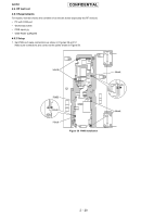
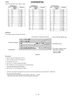
4.6. RF test tool
4.6.1 Requirements
For repairs, this test checks the condition of an electric board (especially the RF section).
•
PC with COM port
•
GX30 Data Cable
•
PWB repair jig
•
GSM Tester (CMU200)
4.6.2 Setup
1.
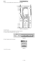
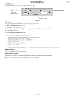
Set PWB and make connections as shown in Figures 56 and 57.
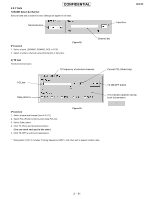
Make sure connections are correct at the points shown in Figure 58.
Figure 56
PWB installation
Hook
Hook
Hook
PWB
Hook
Hook
Hook