Sharp XG-P25X XG-P25X Operation Manual - Page 74
Wired Remote Control Terminal Specifications
 |
View all Sharp XG-P25X manuals
Add to My Manuals
Save this manual to your list of manuals |
Page 74 highlights
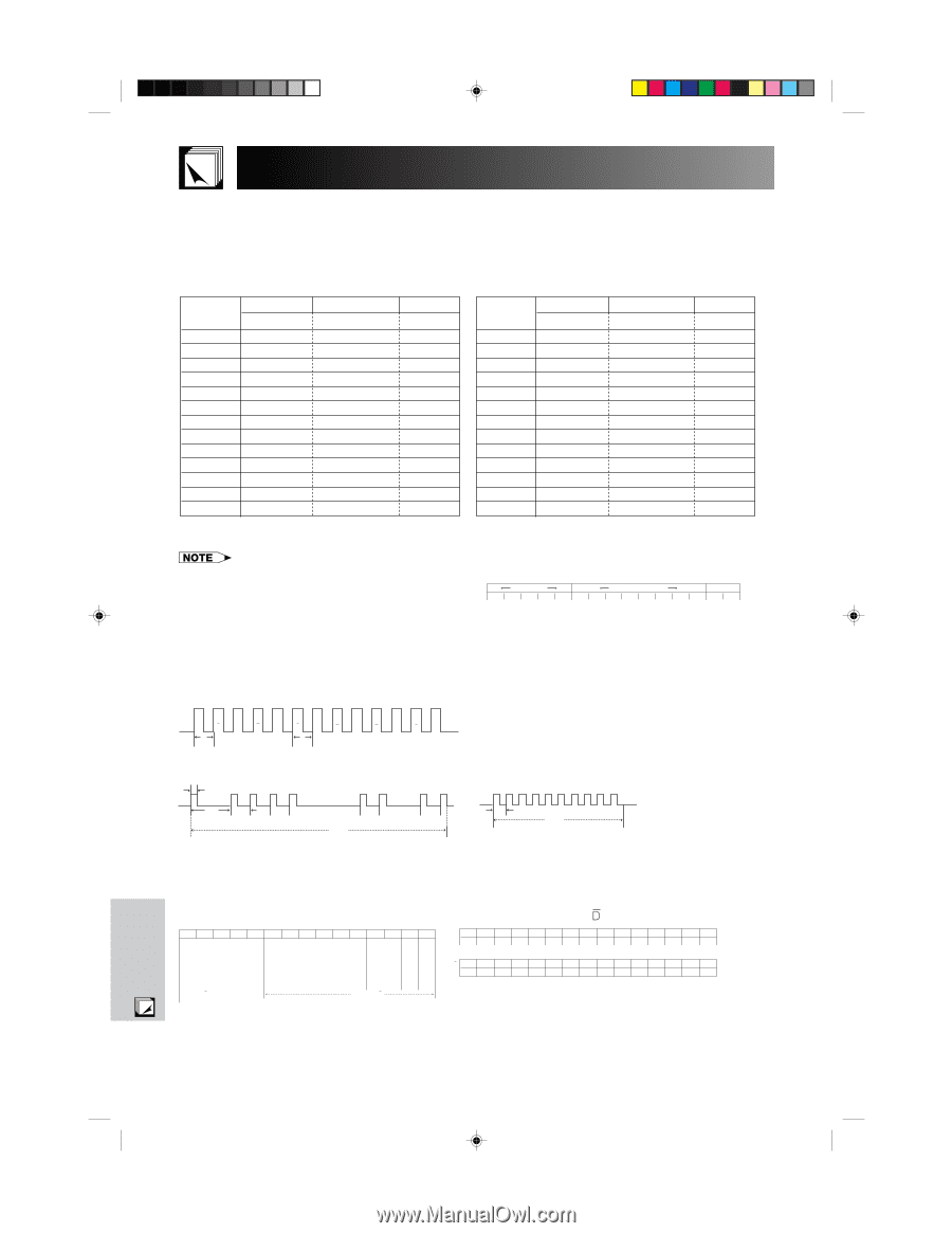
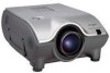
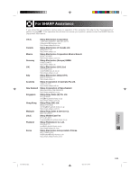
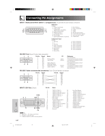
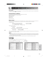
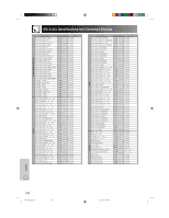
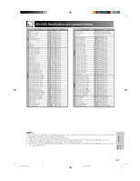
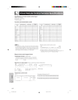
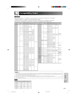
Wired Remote Control Terminal Specifications Specifications of wired remote control input • ø3.5 mm minijack • External: ם5 V (1 A) • Internal: GND Function and transmission codes CONTROL ITEM SYSTEM CODE DATA CODE EXTERNAL CODE C1 C2 C3 C4 C5 C6 C7 C8 C9 C10 C11 C12 C13 C14 C15 ON 1 0 1 1 00 1 1 0 10 1 0 1 0 OFF 1 0 1 1 00 1 1 0 10 0 1 1 0 VOLUME ם 1 0 1 1 00 0 1 0 10 0 0 1 0 VOLUME מ 1 0 1 1 01 0 1 0 10 0 0 1 0 MUTE 1 0 1 1 01 1 1 0 10 0 0 1 0 MENU 1 0 1 1 00 0 1 0 00 1 1 1 0 LENS 1 0 1 1 01 1 0 1 00 0 1 1 0 BLACK SCREEN 1 0 1 1 0 1 0 0 1 0 1 1 0 1 0 ENTER 1 0 1 1 01 1 1 0 10 1 0 1 0 RESIZE 1 0 1 1 00 1 1 1 10 1 0 1 0 UNDO 1 0 1 1 01 0 0 1 10 1 0 1 0 Freeze 1 0 1 1 01 0 1 1 00 0 1 1 0 Break Timer 1 0 1 1 00 0 1 0 11 0 1 1 0 CONTROL ITEM Enlargeם Enlargeמ AUTO SYNC GAMMA INPUT 1 INPUT 2 INPUT 3 INPUT 4 INPUT 5 SYSTEM CODE DATA CODE EXTERNAL CODE C1 C2 C3 C4 C5 C6 C7 C8 C9 C10 C11 C12 C13 C14 C15 1 0 1 1 01 0 1 1 01 1 0 1 0 1 0 1 1 01 0 1 1 01 0 1 1 0 1 0 1 1 00 1 0 1 11 1 1 1 0 1 0 1 1 00 0 1 1 10 0 1 1 0 1 0 1 1 01 0 1 1 10 0 1 1 0 1 0 1 1 00 0 0 0 10 1 0 1 0 1 0 1 1 01 1 1 1 00 1 0 1 0 1 0 1 1 00 0 0 0 00 1 0 1 0 1 0 1 1 01 0 1 0 11 0 0 1 0 1 0 1 1 00 1 1 0 11 0 0 1 0 1 0 1 1 01 0 1 0 11 0 1 1 0 1 0 1 1 00 1 0 0 11 0 0 1 0 1 0 1 1 01 1 0 0 11 0 0 1 0 • To operate the mouse, left-click and right-click functions through the wired remote control input, connect the cable from the WIRED REMOTE control input terminal on the projector to the remote control. The codes for these functions are complex and are, therefore, not listed here. Wired remote control function code LSB C1 System Code C5 C6 Data Code 1 0 1 1 0 * * * * * * * MSB C13 C14 C15 * 1 0 • System codes C1 to C5 are fixed at "10110". • Codes C14 and C15 are reverse confirmation bits, with "10" indicating "Front" and "01" indicating "Rear". Sharp remote control signal format Transmission format: 15-bit format D D D D D D D D D D D D D 67.5 ms 67.5 ms Wave form of output signal: Output using Pulse Position Modulation t T1 T0 "1" "0" "0" "0" 26.4 µs "0" "1" "0" t D • t ס264 µs • T0 ס1.05 ms • T1 ס2.10 ms • Pulse carrier frequency ס455/12 kHz • Duty ratio ס1:1 Transmission control code 15 bit C1 C2 C3 C4 C5 C6 C7 C8 C9 C10 C11 C12 C13 C14 C15 System Address Function Key Data Bit Data Expansion Mask Data Deter- mination Example of Reverse D to D C1 C2 C3 C4 C5 C6 C7 C8 C9 C10 C11 C12 C13 C14 C15 1 0 1 1 0 1 0 0 0 0 0 0 0 1 0 D C1 C2 C3 C4 C5 C6 C7 C8 C9 C10 C11 C12 C13 C14 C15 1 0 1 1 0 0 1 1 1 1 1 1 1 0 1 D to D Common Data Bit Reverse in D Appendix E-71 XG-P25X/CD (E)-h 71 02.3.19, 7:13 PM
-
 1
1 -
2
-
3
-
4
-
5
-
6
-
7
-
8
-
9
-
10
-
11
-
12
-
13
-
14
-
15
-
16
-
17
-
18
-
19
-
20
-
21
-
22
-
23
-
24
-
25
-
26
-
27
-
28
-
29
-
30
-
31
-
32
-
33
-
34
-
35
-
36
-
37
-
38
-
39
-
40
-
41
-
42
-
43
-
44
-
45
-
46
-
47
-
48
-
49
-
50
-
51
-
52
-
53
-
54
-
55
-
56
-
57
-
58
-
59
-
60
-
61
-
62
-
63
-
64
-
65
-
66
-
67
-
68
-
 69
69 -
 70
70 -
 71
71 -
 72
72 -
 73
73 -
 74
74 -
 75
75 -
 76
76 -
 77
77 -
 78
78 -
 79
79 -
80
 |
 |