Toshiba P47LSB User Manual - Page 28
Setting ID
 |
View all Toshiba P47LSB manuals
Add to My Manuals
Save this manual to your list of manuals |
Page 28 highlights
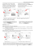
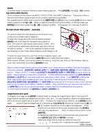
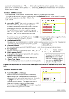
RS232C control When [OFFSET] or [GAIN] Button is clicked in adjust mode the 1st entry will indicate the "red" adjustment or default adjustment. In this case, we use the push [up] / [down] buttons located on the right side of the wired remote control to do an adjustment, then press [ADJ.G] or [ADJ.B] button for other color selection. No other buttons be functional except other adjustment modes. This means, from Contrast adjustment mode, we can enter to brightness or others but not for inputs. The clock and phase are only for RGB input. Color, Tint and Sharpness are for video input only adjustments. Saving adjustments Adjusted value is saved in non-volatile memory when [WRITE] button is clicked. If the newly adjusted value is not acceptable, simply shutting off the power by the rocker switch will erase it and go back to "before adjustment" value. After [WRITE] button is used, the monitor would back to Normal Mode. Adjustment parameters All parameters except 'Magnification' and 'Position' can be adjusted using the right side buttons as: buttons. The 'Position' or 'Magnification' are adjusted using the left side buttons by software, by remote control, use . Setting ID When panels are installed, before doing adjustments, it is necessary to assign an ID number since the new sets do not have any ID number already assigned. The ID number area is 2 digits. 00 to 99 and AA to FF are possible to use. Mixing these numbers such as A0, A1 --- A9, AA will indicate A-10 and AF will be A-16. The same extension applies for B1, B2 - BF up to FF, totaling 256 sets with an assigned ID. Before assigning ID, it is necessary to wire RS232C cable from PC (Video Wall Controller software installed) and RJ45 link. With the new wireless remote control, it is also possible to assign ID number. To assign an ID number, we need to enter [ADJUST] mode at first with ** selection of ID area by software. Then, click [ID ALL] button to enter ID mode, OSD becomes as shown in below left. This is the page to type ID number. In case of the new Remote Control, simply press [ADJUST] then [ID]. If typed wrong, just over-write the number until the right number is obtained. Any number selected from 0 to F will work fine. This example is typed as 01 for ID #. With this left example, own ID = not assigned Typed ID = 01 After typing 01 (ID), then [ID.SET] is to be used to set own ID. Pressing the [ID.SET] button will add own ID number to the 1st (master) panel. After this operation, all the other ID numbers for the remaining panels need to be assigned. Enter ID mode again by pressing [ADJUST], [ID.ALL] buttons to have the input ID number page appear again. Now type in a different number from master panel, such as 02, this is displayed on the 1st and 2nd panels. 28
-
 1
1 -
2
-
3
-
4
-
5
-
6
-
7
-
8
-
9
-
10
-
11
-
12
-
13
-
14
-
15
-
16
-
17
-
18
-
19
-
20
-
21
-
22
-
 23
23 -
 24
24 -
 25
25 -
 26
26 -
 27
27 -
 28
28 -
 29
29 -
 30
30 -
 31
31 -
 32
32 -
 33
33 -
34
-
35
-
36
-
37
-
38
-
39
-
40
-
41
-
42
-
43
-
44
-
45
-
46
 |
 |
