Toshiba P47LSB User Manual - Page 29
Adjust Mode
 |
View all Toshiba P47LSB manuals
Add to My Manuals
Save this manual to your list of manuals |
Page 29 highlights
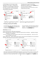
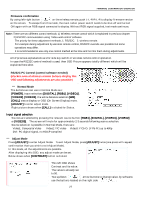
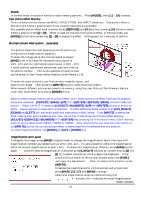
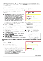
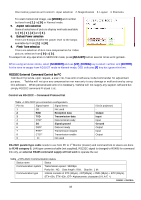
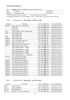
RS232C CONTROL Press the [ID.SET] button. The master panel whose ID is already assigned will not respond but the 2nd panel without an ID # will activate to have ID.02. The same method is used to assign ID numbers to all the remaining panels. Do not use the same ID number to the different panels, since individual adjustment cannot be done. There is no need to disconnect all the RJ45 control links to assign ID, the ID # can be set one by one in the Link connection order. In case of the new wireless remote control, operation is different from above method, use buttons as: [ADJUST] [ID] [NUMBER] "0" appears [ENTER] [UP] "1" appears [ENTER] [ID SET] Bring the wireless remote to the place at the IR sensor for each set and do the same to assign. Using RS232C Link will enter little more difficulty, assigning in front of each panel will end up much efficient ID numbering. To escape from this ID mode, select 'Input ID number' page and use [ADJUST] button. When a panel ID is already set, you can change it by using the same procedure. Go to ID mode, open 'Input ID number' page, and then press the [ID.CLR] button. The OSD will indicate _ _ at the ID number area. Now the new ID can be set after the old ID was erased. Each panel should have one ID number assigned. Avoid using the same # on different panels as this will make it difficult to perform certain adjustments. Once ID number is set, it will remain (even after factory reset or firmware rewrite) until ID be re-assigned. Clearing I.D. Press [ADJUST] to enter Adjust Mode and then press [ID.ALL] to enter ID Mode, in the Input ID Number Page, then press [ID.CLR] to erase the current I.D. number. By wireless remote, [ADJUST] [ID] [ID CLR]. Setting I.D. Press [ID.ALL] so that 'INPUT ID NUMBER' appears and enter the desired 2 digits I.D. using the alpha-numeric keys. Press [ID.SET] to assign the I.D. - the OSD will disappear and the unit will return to Normal Mode. By wireless remote: [ADJUST] [ID] [NUMBER] "0" [UP] # [ENTER] [UP] # [ENTER] [ID SET] Selecting I.D. If using Cube Commander software simply select the two digits I.D. for the cube you wish to control. If [ID.ALL] is pressed instead of an alpha-numeric key '*' will appear, pressing [ID.ALL] twice will display '**' (two wild cards) which will allow to control of all units simultaneously. Wireless remote will not create RS232C code so that RJ-45 link will not work to send commands to the other panel, ID numbering and special adjustments such as Lamp ballast power, picture effect memory and others are possible but not for use of all the panel ** adjustments, use PC and RS232C for such. *** Adjust Mode Some adjustments have already been explained in previous pages. Below are more adjustments performed in Adjust Mode. White Balance adjustment There are five independent memories for white balance selection. Press WB in NORMAL mode to select the desired memory (WB1 - 5) before making adjustments. It is recommended to use USER position to make adjustments since others are pre-set to each color temperature. RS232C CONTROL 29
-
 1
1 -
2
-
3
-
4
-
5
-
6
-
7
-
8
-
9
-
10
-
11
-
12
-
13
-
14
-
15
-
16
-
17
-
18
-
19
-
20
-
21
-
22
-
23
-
 24
24 -
 25
25 -
 26
26 -
 27
27 -
 28
28 -
 29
29 -
 30
30 -
 31
31 -
 32
32 -
 33
33 -
 34
34 -
35
-
36
-
37
-
38
-
39
-
40
-
41
-
42
-
43
-
44
-
45
-
46
 |
 |
