Toshiba Satellite A300 Maintenance Manual
Toshiba Satellite A300 Manual
 |
View all Toshiba Satellite A300 manuals
Add to My Manuals
Save this manual to your list of manuals |
Toshiba Satellite A300 manual content summary:
- Toshiba Satellite A300 | Maintenance Manual - Page 1
Toshiba Personal Computer Satellite A300 Maintenance Manual TOSHIBA CORPORATION File Number 960-Q08 Satellite A300 Maintenance Manual (960-Q08) - Toshiba Satellite A300 | Maintenance Manual - Page 2
Toshiba Personal Computer Washington- Satellite A300 Maintenance Manual First edition Feb 2008 Disclaimer The information presented in this manual has been reviewed and validated for accuracy. The included set of instructions and descriptions are accurate for the Satellite A300 Series at the time of - Toshiba Satellite A300 | Maintenance Manual - Page 3
Preface This maintenance manual describes how to perform hardware service maintenance for the Toshiba Personal Computer Satellite A300 Series. The procedures described in this manual are intended to help service technicians isolate faulty Field Replaceable Units (FRUs) and replace them in the field. - Toshiba Satellite A300 | Maintenance Manual - Page 4
describes the Satellite A300 system unit and each FRU. Chapter 2 Troubleshooting Procedures explains how to diagnose and resolve FRU problems. Chapter 3 Test and Diagnostics describes how to perform test and diagnostic operations for maintenance service. Chapter 4 Replacement Procedures - Toshiba Satellite A300 | Maintenance Manual - Page 5
third. User input Text that you are instructed to type in is shown in the boldface type below: DISKCOPY A: B: The display Text generated by the computer that appears on its display is presented in the typeface below: Format complete System transferred Satellite A300 Maintenance Manual (960-Q08) 5 - Toshiba Satellite A300 | Maintenance Manual - Page 6
Troubleshooting ...1 2.2 Troubleshooting Flowchart 3 2.3 Power Supply Troubleshooting 7 Procedure 1 Power Status Check 7 Procedure 2 Error Code Check 9 Procedure 3 Connection Check 10 Procedure 4 Charging Check 11 Procedure 5 Replacement Check 12 Satellite A300 Maintenance Manual - Toshiba Satellite A300 | Maintenance Manual - Page 7
1 Diagnostic Test Program Execution Check 31 Procedure 2 Connector Check and Replacement Check 32 2.8 Touch pad Troubleshooting 33 Procedure 1 Diagnostic Test Program Execution Check 33 Procedure 2 Connector Check and Replacement Check 34 Satellite A300 Maintenance Manual (960-Q08) 7 - Toshiba Satellite A300 | Maintenance Manual - Page 8
1 Diagnostic Test Program Execution Check 49 Procedure 2 Connector Check and Replacement Check 49 2.17 Bluetooth Troubleshooting 50 Procedure 1 Diagnostic Test Program Execution Check 50 Procedure 2 Connector Check and Replacement Check 50 Satellite A300 Maintenance Manual (960-Q08) - Toshiba Satellite A300 | Maintenance Manual - Page 9
3-55 3.18 Log Utilities ...3-57 3.18.1...... Operations 3-57 3.19 System Configuration 3-59 3.20 Running Test Edit Item 3-60 3.20.1...... Function Description 3-60 3.20.2 Operation Description 3-60 3.21 Common Tests an Operation 3-62 Satellite A300 Maintenance Manual (960-Q08) 9 - Toshiba Satellite A300 | Maintenance Manual - Page 10
Board ...4-24 4.9 Optical disk drive...4-26 4.10 Display assembly ...4-28 4.11 Bluetooth assembly 4-33 4.12 Cover assembly...4-38 4.13 Touch pad...4-40 4.14 Audio board ...4-40 4.15 Fingerprint board ...4-41 4.16 USB board...4-42 4.17 System board...4-45 Satellite A300 Maintenance Manual (960-Q08) - Toshiba Satellite A300 | Maintenance Manual - Page 11
4.18 CPU...4-47 4.19 VGA heat sink...4-50 4.20 LCD unit / FL inverter 4-52 Satellite A300 Maintenance Manual (960-Q08) 11 - Toshiba Satellite A300 | Maintenance Manual - Page 12
B-1 Appendix C Pin Assignments C-1 Appendix D Keyboard Scan/Character Codes D-1 Appendix E Key Layout...E-1 Appendix F Wiring Diagrams F-1 Appendix G BIOS Rewrite Procedures G-1 Appendix H EC/KBC Rewrite Procedures H-1 Appendix I Reliability...I-1 Satellite A300 Maintenance Manual (960-Q08) - Toshiba Satellite A300 | Maintenance Manual - Page 13
Satellite A300 Maintenance Manual (960-Q08) 13 - Toshiba Satellite A300 | Maintenance Manual - Page 14
Chapter 1 Hardware Overview Satellite A300 Maintenance Manual (960-Q08) - Toshiba Satellite A300 | Maintenance Manual - Page 15
Chapter 1 1 Hardware Overview Hardware Overview Satellite A300 Maintenance Manual (960-Q08) ii - Toshiba Satellite A300 | Maintenance Manual - Page 16
Drive 15 1.5 Keyboard...18 1.6 TFT Color Display...19 1.6.1 LCD Module 19 1.6.2 FL Inverter Board 22 1.6.3..... FL Inverter Board 22 1.7 Power Supply ...24 1.8 Batteries ...25 1.8.1 Main Battery 25 1.8.2 Battery Charging Control 26 1.8.3 RTC battery 27 1.9 AC Adapter ...28 Satellite A300 - Toshiba Satellite A300 | Maintenance Manual - Page 17
FL inverter board specifications-Dual lamp 23 Power supply output rating 24 Battery specifications 25 Time required for charges of main battery 26 Data preservation time 26 Time required for charges of RTC battery 27 AC adapter specifications 28 Satellite A300 Maintenance Manual (960-Q08) iv - Toshiba Satellite A300 | Maintenance Manual - Page 18
Overview Features 1.1 Features The Satellite A300 series are 2 spindle PCs running Microprocessor Microprocessor that is used will be different by the model. It supports processors as follows Intel Core2 Duo Processor FSB : 667 MHz FSB ) 570(2.26GHz) Satellite A300 Maintenance Manual (960-Q08) 1 - Toshiba Satellite A300 | Maintenance Manual - Page 19
. CRT Supported via a RGB connector. θ Keyboard Toshiba Standard keyboard with 86-88 keys (desktop-style), Support Windows keys & Application keys. (Toshiba standard layout) Standard pitch, 2.5mm travel length. Multi-langue support θ New Dummy card slot Satellite A300 Maintenance Manual (960 - Toshiba Satellite A300 | Maintenance Manual - Page 20
. θ Wireless LAN The wireless LAN is equipped on the mini card slot. θ LAN/MODEM Connectors for LAN and Modem are separately mounted. θ 1394 One 1394 port is equipped. θ Multiple Digital Media Card Slot XD/MS/MS pro/SD/MMC are supported θ Bluetooth Satellite A300 Maintenance Manual (960-Q08 - Toshiba Satellite A300 | Maintenance Manual - Page 21
Chapter 1 Hardware Overview USB Bluetooth Module standard Ver 2.1 & EDR(Enhanced Data Rate) equipped θ Security Kensington Lock, Fingerprint -Enhanced Lock is also equipped. θ HDD Password θ 3D Accelerometer for HDD Figure 1-1 Front of the computer Satellite A300 Maintenance Manual (960-Q08) 4 - Toshiba Satellite A300 | Maintenance Manual - Page 22
Chapter 1 Hardware Overview Satellite A300 Maintenance Manual (960-Q08) 5 - Toshiba Satellite A300 | Maintenance Manual - Page 23
Chapter 1 Hardware Overview 1.2 System Block Diagram Figure 1-2 shows the system block diagram. Figure 1-2 System block diagram for Intel Platform Satellite A300 Maintenance Manual (960-Q08) 6 - Toshiba Satellite A300 | Maintenance Manual - Page 24
of accepting DDRII-SDRAM 512MB,1GB or 2GB memory modules for a maximum of 4GB(2GB for GL960). • 200-pin SO-DIMM • 1.8V operation θ BIOS ROM (Flash memory) • 8Mbit θ Chipset (Santa Rosa Platform) This gate array has the following elements and functions. Satellite A300 Maintenance Manual (960-Q08) 7 - Toshiba Satellite A300 | Maintenance Manual - Page 25
• 10/100 LAN controller (Marvell 88E8040T-A0-NNC1C000) • GIGA LAN controller (Marvell 88E8072-B1-NNC1C000) θ Mini Card Wireless LAN card (BTO) 5.4 GHz DSSS/OFDM LAN card is equipped. Conformity with IEEE 802.11b/g, IEEE 802.11 a/g/n and IEEE 802.11a/b/g.. Satellite A300 Maintenance Manual (960-Q08 - Toshiba Satellite A300 | Maintenance Manual - Page 26
FAX transmission is available. Supports ITU-TV.90. The transfer speed of data receiving is 56kbps, of data sending is 33.6kbps and of FAX is 14.4kbps. Actual speed depends on the quality of the line used. Connected to telephone line through RJ11 MOD Satellite A300 Maintenance Manual (960-Q08) 9 - Toshiba Satellite A300 | Maintenance Manual - Page 27
Chapter 1 Hardware Overview 1.3 2.5-inch Hard Disk Drive A compact, high-capacity HDD with a height of 9.5mm. Contains a 2.5-inch magnetic disk and magnetic heads. Figure 1-3 shows a view FUJITSU MHY2200BH 100 9.5 70 101(Max) FUJITSU MHY2250BH Satellite A300 Maintenance Manual (960-Q08) 10 - Toshiba Satellite A300 | Maintenance Manual - Page 28
dimensions Parameter Outline dimensi ons Width (mm) Height (mm) Depth (mm) Weight (g) FUJITSU MHX2250BT Standard value FUJITSU MHX2300BT 100 12.5 70.0 101(Max) FUJITSU MHZ2400BT Satellite A300 Maintenance Manual (960-Q08) 11 - Toshiba Satellite A300 | Maintenance Manual - Page 29
(read) (ms) Power-on-to-ready (sec) FUJITSU MHY2120BH 80GB 12 3.5(typ)/9.5(Max) Specification FUJITSU MHY2160BH 120GB FUJITSU MHY2200BH 200GB 5,400 84.6MB/s Max. 1.5Gbps (150MB/s) 1.5Gbps(150MB/s) 12.0ms/14.0ms 4.0 (typ.) FUJITSU MHY2250BH 250GB Satellite A300 Maintenance Manual (960-Q08 - Toshiba Satellite A300 | Maintenance Manual - Page 30
rate (MB/s) Average random seek time (read) (ms) Power-on-to-ready (sec) FUJITSU MHX2250BT 250GB Specification FUJITSU MHX2300BT 300GB 4,200 FUJITSU MHZ2400BT 400GB 60.8MB/s Max. 1.5Gbps (150MB/s) 1.5Gbps (150MB/s) 12.0ms/14.0ms 4.0 (typ) Satellite A300 Maintenance Manual (960-Q08) 13 - Toshiba Satellite A300 | Maintenance Manual - Page 31
Chapter 1 Hardware Overview 1.4 Optical Drive Satellite A300 Maintenance Manual (960-Q08) 14 - Toshiba Satellite A300 | Maintenance Manual - Page 32
RAM. It is a high-performance drive that reads DVD-ROM at maximum 8-speed and CD at maximum 24-speed. Write speed of DVD±R/±RW and DVD-RAM is different depending on the drive. The DVD Super Multi drive 104 104 176.2 PNR DVRKD08TBL 128 12.7 134 176.2 Satellite A300 Maintenance Manual (960-Q08) 15 - Toshiba Satellite A300 | Maintenance Manual - Page 33
.140(CD-ROM Mode 1 Disc is used) Ave.150 Ave.150 (DVD-ROM Single (DVD-ROM Single Layer Disc is used) Layer Disc is use Satellite A300 Maintenance Manual (960-Q08) 16 - Toshiba Satellite A300 | Maintenance Manual - Page 34
) 4.7G DVD+R/RW (Read & Write) DVD+-R Dual (Read & Write) DVD-RAM (Read & Write) 80mm DVD DVD (DVD-5; Single layer, Single side 4.7Gbytes) DVD (DVD-9; Dual layer, Single DVD (DVD-5; Single layer, Single side 4.7Gbytes) DVD (DVD-9; Dual layer, Single Satellite A300 Maintenance Manual (960-Q08) 17 - Toshiba Satellite A300 | Maintenance Manual - Page 35
1 Hardware Overview 1.5 Keyboard The Satellite A300 keyboard has one kind of placement that is for US/UK style. Figure 1-5 is a view of the keyboard for US/UK style Figure 1-5 Keyboard for US/UK style See Appendix E for details of the keyboard layout. Satellite A300 Maintenance Manual (960-Q08) 18 - Toshiba Satellite A300 | Maintenance Manual - Page 36
The Satellite A300 Panel has two different kinds of model, one is single lamp LCD and the other is dual lamp LCD. 1.6.1 LCD Module with Single lamp Figure 1-6 ~ 1-9 shows a view of the LCD module and Table 1-5-1 lists the specifications. Figure 1-6 AUO LCD Module Satellite A300 Maintenance Manual - Toshiba Satellite A300 | Maintenance Manual - Page 37
Chapter 1 Hardware Overview Figure 1-7 CMO LCD Module Figure 1-8 LG LCD Module Satellite A300 Maintenance Manual (960-Q08) 20 - Toshiba Satellite A300 | Maintenance Manual - Page 38
Module Table 1-5-1 LCD module specifications (Single) Item Number of Dots Dot spacing (mm) LG LP154WX4TLC8 Specifications(WXGA) Samsung AUO B154EW08 LTN154AT07-T01 V1 1,280x 800 CMO N154I3-L03 0.2588(H)× 0.2588(V) Satellite A300 Maintenance Manual (960-Q08) 21 - Toshiba Satellite A300 | Maintenance Manual - Page 39
specifications-Single lamp Item Input Output Voltage (V) Power (W) Voltage (Vrms) Foxconn T18I095.00 8~20 7.5W 612~945 Specifications Delta DAC-08N035 AF 8~20 SUMIDA TWS-449-308 7~20 7.5W 7.5W 612~945 612~945 TDK TBD485NR 8~20 7.5W 612~945 Satellite A300 Maintenance Manual (960-Q08) 22 - Toshiba Satellite A300 | Maintenance Manual - Page 40
specifications-Dual lamp Item Input Output Voltage (V) Power (W) Voltage (Vrms) Current (f=55KHz)(mArms) Foxconn T18I096.00 8~20 7.5W 612~945 Specifications SUMIDA TWS-449-309 8~20 7.5W 612~945 2.3±0.4 ~ 6.5±0.3 TDK TBD487NR 8~20 7.5W 612~945 Satellite A300 Maintenance Manual (960-Q08) 23 - Toshiba Satellite A300 | Maintenance Manual - Page 41
3.1~5 3.3 3.3 3.3 3.3 3.3 3.3 1.8 1.5 1.25 1.05 0.55~1.575 Power supply (Yes/No) Power OFF Suspend mode Power OFF Boot mode Yes Yes Yes No No No No No No No No No No No Battery No No No No No No Yes No No No No No No No No No No No No Satellite A300 Maintenance Manual (960-Q08) - Toshiba Satellite A300 | Maintenance Manual - Page 42
ion Lithium ion 10.8v 10.8v 3V 4000mAh 6000mAh 17mAh 1.8.1 Main Battery The main battery is the primary power supply for the computer when the AC adapter is not connected. In Standby, the main battery maintains the current status of the computer. Satellite A300 Maintenance Manual (960-Q08) 25 - Toshiba Satellite A300 | Maintenance Manual - Page 43
Battery Charge When the AC adapter is connected, normal charging is used while the system is turned on and quick charge is used while the system is turned off. Refer to the following Table 1-8. Table 1-8 Time required for charges of main battery Condition Power On Charge Power Off Charge Charging - Toshiba Satellite A300 | Maintenance Manual - Page 44
1-10 lists the Time required for charges of RTC battery and data preservation time. Table 1-10 Time required for charges of RTC battery Condition Power ON (Lights Power LED) Data preservation tome (Full-charged) Time About 24 hours About a month Satellite A300 Maintenance Manual (960-Q08) 27 - Toshiba Satellite A300 | Maintenance Manual - Page 45
11 AC adapter specifications Parameter With Led Specification DELTA/ LITE-ON DELTA/ LITE-ON DELTA/ LITE-ON Power Input voltage Input frequency Input current Output voltage Output current 75W 3.95A 90W AC 100V/240V 50Hz/60Hz ≦ 1.5A DC 19V 4.74A 120W 6.3A Satellite A300 Maintenance Manual (960 - Toshiba Satellite A300 | Maintenance Manual - Page 46
θ VRAM Satellite A300 (10A): Shared with System RAM for AMD RS690M. Satellite A300 (10AG): M82XT Graphic card:64MB,256MB,512MB; θ HDD (First/Second Hard Drive - SATA) 5400RPM: 120GB, 160GB, 250GB, 320GB, internal drives. 2.5 inch x 9.5mm height. 4200RPM: 200GB, 250GB, 300G, 400G, internal driver - Toshiba Satellite A300 | Maintenance Manual - Page 47
via a RGB connector. - HDMI Satellite A300 (10A): No supported Satellite A300 (10AG): Supported via a HDMI TYPE-A connector - S-Video Supported via a 4-pins S-Video connector θ Keyboard Toshiba Standard keyboard with 86-88 keys (desktop-style), Support Windows keys & Application keys. (Toshiba - Toshiba Satellite A300 | Maintenance Manual - Page 48
). θ Wireless LAN The wireless LAN is equipped on the mini card slot. θ LAN/MODEM Connectors for LAN and Modem are separately mounted. θ 1394 One 1394 port is equipped. θ Multiple Digital Media Card Slot XD/MS/MS pro/SD/MMC are supported θ Bluetooth Satellite A300 Maintenance Manual (960-Q02 - Toshiba Satellite A300 | Maintenance Manual - Page 49
Chapter 1 Hardware Overview USB Bluetooth Module (BTO) V2.1 & EDR(Enhanced Data Rate) equipped θ Security Kensington Lock, Fingerprint -Enhanced Lock is also equipped. HDD Password Figure 1-1 Front of the computer Satellite A300 Maintenance Manual (960-Q02) 4 - Toshiba Satellite A300 | Maintenance Manual - Page 50
1.2 System Block Diagram Figure 1-2 shows the system block diagram. Chapter 1 Hardware Overview Figure 1-2 System block diagram for AMD Platform Satellite A300 Maintenance Manual (960-Q02) 5 - Toshiba Satellite A300 | Maintenance Manual - Page 51
200-pin SO-DIMM • 1.8V operation θ BIOS ROM (Flash memory) • 8Mbit - SPI interface support − PCI Express Interface 1.1a support − A-Link Express II Interface − 465-ball 21 x 21mm FC-BGA Package • South Bridge (AMD SB600) − A-Link Express II Interface (1/2/4-lane) Satellite A300 Maintenance Manual - Toshiba Satellite A300 | Maintenance Manual - Page 52
modem supports V.92/V.90 analog receive data up to 56 kbps with V.44 data compression, V.17 analog fax to 14.4 kbps, voice/telephone answering machine (TAM), high quality soft speakerphone. θ Bluetooth USB Bluetooth Module. Bluetooth standard V2.1 +EDR conformity. Satellite A300 Maintenance Manual - Toshiba Satellite A300 | Maintenance Manual - Page 53
1.3 2.5-inch Hard Disk Drive A compact, high-capacity HDD with a height of 9.5mm. Contains a 2.5-inch magnetic disk and magnetic heads. Figure 1-3 shows a view of the 2.5-inch HDD and Tables 1-1 and 1-2 list the specifications. Figure 1-3 2.5-inch HDD Satellite A300 Maintenance Manual (960-Q02 - Toshiba Satellite A300 | Maintenance Manual - Page 54
HTS542520k9SA 00 HITACHI HTS542525k9S A00 69.85 +/- 0.25 9.5 100.2 +/- 0.25 95 (max.) 95 (max.) 102 (max.) 102 (max.) Table 1-2 2.5-inch HDD dimensions Parameter Standard value Satellite A300 Maintenance Manual (960-Q02) 9 - Toshiba Satellite A300 | Maintenance Manual - Page 55
MK2546G SX 160GB 200GB 5,400 250 GB 730Mbits Media 300MBytes Host TOSHIBA MK3252G SX 320GB 794Mbits Media 3GBytes Host bus transfer rate (MB/s) 1.5Gbps(150MB/s) Average random seek time (read) (ms) Power-on-to-ready (sec) 12 3.5(typ)/9.5(Max) Satellite A300 Maintenance Manual (960-Q02) 10 - Toshiba Satellite A300 | Maintenance Manual - Page 56
(RPM) 5,400 Data transfer Rate - To/From Media - T0/From Host 65.5MB/s 1.5Gbps 65.5MB/s 1.5Gbps 65.5MB/s 1.5Gbps 65.5MB/s 1.5Gbps bus transfer rate (MB/s) 150 (MB/s Average random seek time 11 (read) (ms) Power-on-to-ready (sec) 3.5 sec Satellite A300 Maintenance Manual (960-Q02) 11 - Toshiba Satellite A300 | Maintenance Manual - Page 57
rate (MB/s) Average random seek time (read) (ms) Power-on-to-ready (sec) FUJITSU MHX2250BT 250GB Specification FUJITSU MHX2300BT 300GB 4,200 FUJITSU MHZ2400BT 400GB 60.8MB/s Max. 1.5Gbps (150MB/s) 1.5Gbps (150MB/s) 12.0ms/14.0ms 4.0 (typ) Satellite A300 Maintenance Manual (960-Q02) 12 - Toshiba Satellite A300 | Maintenance Manual - Page 58
1.4 Optical Drive Chapter 1 Hardware Overview Satellite A300 Maintenance Manual (960-Q02) 13 - Toshiba Satellite A300 | Maintenance Manual - Page 59
RAM. It is a high-performance drive that reads DVD-ROM at maximum 8-speed and CD at maximum 24-speed. Write speed of DVD±R/±RW and DVD-RAM is different depending on the drive. The DVD Super Multi drive 104 104 176.2 PNR DVRKD08TBL 128 12.7 134 176.2 Satellite A300 Maintenance Manual (960-Q02) 14 - Toshiba Satellite A300 | Maintenance Manual - Page 60
drive specifications (1/4) Drive Specification Parameter TST TST PNR PNR TS-L632H TS-L632P DVR-KD08TBT DVR-KD08TBL Read (KB/s) CD-ROM 3600 KB/s CD-R 3600 KB/s CD-RW 3600 KB/s DVD-ROM(L) 10800 KB/s DVD+/-R Dual8100KB/s DVD-RAM Not Support DVD Satellite A300 Maintenance Manual (960-Q02) 15 - Toshiba Satellite A300 | Maintenance Manual - Page 61
) 4.7G DVD+R/RW (Read & Write) DVD+-R Dual (Read & Write) DVD-RAM (Read & Write) 80mm DVD DVD (DVD-5; Single layer, Single side 4.7Gbytes) DVD (DVD-9; Dual layer, Single DVD (DVD-5; Single layer, Single side 4.7Gbytes) DVD (DVD-9; Dual layer, Single Satellite A300 Maintenance Manual (960-Q02) 16 - Toshiba Satellite A300 | Maintenance Manual - Page 62
Chapter 1 Hardware Overview 1.5 Key board The Satellite A300 keyboard has one kind of placement; one is for US/UK style Figure 1-5 is a view of the keyboard for US style Figure 1-5 Keyboard for US/UK style Satellite A300 Maintenance Manual (960-Q02) 17 - Toshiba Satellite A300 | Maintenance Manual - Page 63
The Satellite A300 Panel has two different kinds of model, one is single lamp LCD and the other is dual lamp LCD. 1.6.1 LCD Module with Single lamp Figure 1-6 ~ 1-9 shows a view of the LCD module and Table 1-5-1 lists the specifications. Figure 1-6 AUO LCD Module Satellite A300 Maintenance Manual - Toshiba Satellite A300 | Maintenance Manual - Page 64
Chapter 1 Hardware Overview Figure 1-7 CMO LCD Module Figure 1-8 LG LCD Module Satellite A300 Maintenance Manual (960-Q02) 19 - Toshiba Satellite A300 | Maintenance Manual - Page 65
Module Table 1-5-1 LCD module specifications (Single) Item Number of Dots Dot spacing (mm) LG LP154WX4TLC8 Specifications(WXGA) Samsung AUO B154EW08 LTN154AT07-T01 V1 1,280x 800 CMO N154I3-L03 0.2588(H)× 0.2588(V) Satellite A300 Maintenance Manual (960-Q02) 20 - Toshiba Satellite A300 | Maintenance Manual - Page 66
board specifications. Table 1-5-3 FL inverter board specifications-Single lamp Item Input Voltage (V) Power (W) Foxconn T18I095.00 8~20 7.5W Specifications Delta DAC-08N035 AF 8~20 SUMIDA TWS-449-308 7~20 7.5W 7.5W TDK TBD485NR 8~20 7.5W Satellite A300 Maintenance Manual (960-Q02) 21 - Toshiba Satellite A300 | Maintenance Manual - Page 67
specifications-Dual lamp Item Input Output Voltage (V) Power (W) Voltage (Vrms) Current (f=55KHz)(mArms) Foxconn T18I096.00 8~20 7.5W 612~945 Specifications SUMIDA TWS-449-309 8~20 7.5W 612~945 2.3±0.4 ~ 6.5±0.3 TDK TBD487NR 8~20 7.5W 612~945 Satellite A300 Maintenance Manual (960-Q02) 22 - Toshiba Satellite A300 | Maintenance Manual - Page 68
3.3 3.3 3.3 2.5 1.8 1.8 1.8 1.8 1.5 1.25 1.25 1.0~1.2 0.7~1.2 Power supply (Yes/No) Power OFF Suspend mode Power OFF Boot mode Yes Yes No No Yes Yes Yes No Yes No No No No No No Battery No No No No No No No No No No No No No No No No Satellite A300 Maintenance Manual (960-Q02) 23 - Toshiba Satellite A300 | Maintenance Manual - Page 69
ion Lithium ion 10.8v 10.8v 3V 4000mAh 6000mAh 17mAh 1.8.1 Main Battery The main battery is the primary power supply for the computer when the AC adapter is not connected. In Standby, the main battery maintains the current status of the computer. Satellite A300 Maintenance Manual (960-Q02) 24 - Toshiba Satellite A300 | Maintenance Manual - Page 70
Battery Charge When the AC adapter is connected, normal charging is used while the system is turned on and quick charge is used while the system is turned off. Refer to the following Table 1-8. Table 1-8 Time required for charges of main battery Condition Power On Charge Power Off Charge Charging - Toshiba Satellite A300 | Maintenance Manual - Page 71
1-10 lists the Time required for charges of RTC battery and data preservation time. Table 1-10 Time required for charges of RTC battery Condition Power ON (Lights Power LED) Data preservation tome (Full-charged) Time About 24 hours About a month Satellite A300 Maintenance Manual (960-Q02) 26 - Toshiba Satellite A300 | Maintenance Manual - Page 72
11 AC adapter specifications Parameter With Led Specification DELTA/ LITE-ON DELTA/ LITE-ON DELTA/ LITE-ON Power Input voltage Input frequency Input current Output voltage Output current 75W 3.95A 90W AC 100V/240V 50Hz/60Hz ≦ 1.5A DC 19V 4.74A 120W 6.3A Satellite A300 Maintenance Manual (960 - Toshiba Satellite A300 | Maintenance Manual - Page 73
Chapter 2 Troubleshooting Procedures Satellite A300 Maintenance Manual(960-Q08) - Toshiba Satellite A300 | Maintenance Manual - Page 74
Satellite A300 Maintenance Manual(960-Q08) - Toshiba Satellite A300 | Maintenance Manual - Page 75
Supply Troubleshooting 7 Procedure 1 Power Status Check 7 Procedure 2 Error Code Check 9 Procedure 3 Connection Check 11 Procedure 4 Charging Check 11 Procedure 5 Replacement Check 12 2.4 System Board Troubleshooting 13 Procedure 1 Message Check 14 Procedure 2 Debugging Port - Toshiba Satellite A300 | Maintenance Manual - Page 76
1 Diagnostic Test Program Execution Check 47 Procedure 2 Connector Check and Replacement Check 47 2.16 Bluetooth Troubleshooting 48 Procedure 1 Diagnostic Test Program Execution Check 48 Procedure 2 Connector Check and Replacement Check 48 Satellite A300 Maintenance Manual(960-Q08) - Toshiba Satellite A300 | Maintenance Manual - Page 77
Troubleshooting Chapter 2 describes how to determine which Field Replaceable Unit (FRU) in the computer is causing the computer to malfunction. The FRUs covered are: 1. Power supply 2. System Board 3. USB FDD 4. 2.5" HDD 5. Keyboard 6. Touch pad 7. Display 8. Optical Disk Drive 9. Modem 10. LAN - Toshiba Satellite A300 | Maintenance Manual - Page 78
types of connections in the figure of board and module connection in and after 2.3 Power Supply Troubleshooting. (1) Cable connection is described in the figure as line. (2) Pin connection is described in the figure as arrow. Connection of modem Satellite A300 Maintenance Manual (960-Q08) 2 - Toshiba Satellite A300 | Maintenance Manual - Page 79
the password if a password is registered. ‰ Verify with the customer that Toshiba Windows is installed on the hard disk. Non- Windows operating systems can cause the computer to malfunction. ‰ Make sure all optional equipment is removed from the computer. Satellite A300 Maintenance Manual (960 - Toshiba Satellite A300 | Maintenance Manual - Page 80
2 Troubleshooting Procedures Figure 2-1 Troubleshooting flowchart (1/2) Satellite A300 Maintenance Manual (960-Q08) 4 - Toshiba Satellite A300 | Maintenance Manual - Page 81
2 Troubleshooting Procedures Figure 2-2 Troubleshooting flowchart (2/2) If the diagnostics program cannot detect an error, the problem may be intermittent. The Test program should be executed several times to isolate the problem. Check the Log Utilities Satellite A300 Maintenance Manual (960-Q08) - Toshiba Satellite A300 | Maintenance Manual - Page 82
Section 2.15. 13. If an error is detected on the fingerprint test, perform the fingerprint Troubleshooting Procedures in Section 2.16. 14. If an error is detected on the Bluetooth test, perform the Bluetooth Troubleshooting Procedures in Section 2.17. Satellite A300 Maintenance Manual (960-Q08) 6 - Toshiba Satellite A300 | Maintenance Manual - Page 83
is fully charged and the external DC is input. It has no relation with ON/OFF of the system power. The battery level is low while the system power is ON. The system is driven by only a battery and the battery level is low. Any condition other than those above. Satellite A300 Maintenance Manual (960 - Toshiba Satellite A300 | Maintenance Manual - Page 84
1 If the DC IN icon blinks orange, go to Procedure 2. Check 2 If the DC IN icon does not light, go to Procedure 3. Check 3 If the battery icon does not light orange, go to Procedure 4. NOTE: Use a supplied AC adapter. Satellite A300 Maintenance Manual (960-Q08) 8 - Toshiba Satellite A300 | Maintenance Manual - Page 85
Out Error Other Error Bad Command Error Bad Address Mark Error Record Not Found HDC Not Reset Error Drive Not Initialized DMA Boundary Error Bad Sector Bad Track Error ECC Error ECC Recover Enabled HDC Error Seek Error Time Out Error Drive Not Ready Satellite A300 Maintenance Manual (960-Q08) 9 - Toshiba Satellite A300 | Maintenance Manual - Page 86
2 Troubleshooting Procedures Table 2-3 Error codes and error status names (2/2) Device Name HDD Cache Memory Multimedia Error Drive Drive Not Ready Other Error NOTE: If error status name is Other Error , please reference the Error Code for error information Satellite A300 Maintenance Manual - Toshiba Satellite A300 | Maintenance Manual - Page 87
high or low. Leave the battery for a while to adjust it in the right temperature. If the battery pack is still not charged, go to Check 5. Check 5 Replace the battery pack with a new one. If the battery pack is still not charged, go to Procedure 5. Satellite A300 Maintenance Manual (960-Q08) 11 - Toshiba Satellite A300 | Maintenance Manual - Page 88
a new one. When AC adapter is not connected ; (When driving with battery pack) Check 1 Battery pack may be faulty. Replace it with a new one. If the problem still occurs, perform Check 2. Check 2 System board may be faulty. Replace it with a new one. Satellite A300 Maintenance Manual (960-Q08) 12 - Toshiba Satellite A300 | Maintenance Manual - Page 89
1 and continue with the other procedures as instructed. The procedures described in this section are: Procedure 1: Message Check Procedure 2: Debugging Port Check Procedure 3: Diagnostic Test Program Execution Check Procedure 4: Replacement Check Satellite A300 Maintenance Manual (960-Q08) 13 - Toshiba Satellite A300 | Maintenance Manual - Page 90
instructs. The following error message appears when data stored in RAM under the resume function is lost because the battery has become discharged or the system board is damaged. Go to Procedure 3. WARNING: RESUME FAILURE. PRESS ANY KEY TO CONTINUE. Satellite A300 Maintenance Manual (960-Q08) 14 - Toshiba Satellite A300 | Maintenance Manual - Page 91
(13) DMA PAGE REGISTER ERROR (14) DMAC #1 ERROR (15) DMAC #2 ERROR (16) PIC #1 ERROR (17) PIC #2 ERROR (18) KBC ERROR (19) HDC ERROR (20) HDD #0 ERROR (21) HDD #1 ERROR (22) NO FDD ERROR (23) FDC ERROR (24) TIMER INTERRUPT ERROR (25) RTC UPDATE ERROR Satellite A300 Maintenance Manual (960-Q08) 15 - Toshiba Satellite A300 | Maintenance Manual - Page 92
0Eh Initialize I/O component 0Fh Initialize the local bus IDE 10h Initialize Power Management 11h Load alternate registers with initial POST values 12h Restore CPU control word during warm boot 13h Initialize PCI Bus Mastering devices Satellite A300 Maintenance Manual (960-Q08) 16 - Toshiba Satellite A300 | Maintenance Manual - Page 93
2-1-2-3 Check ROM copyright notice 48h Check video configuration against CMOS 49h Initialize PCI bus and devices 4Ah Initialize all video adapters in system 4Bh QuietBoot start (optional) 4Ch Shadow video BIOS ROM 4Eh Display BIOS copyright notice 50h Display CPU type and speed 51h - Toshiba Satellite A300 | Maintenance Manual - Page 94
Devices (optional) Initialize BIOS Data Area Enable Non-Maskable Interrupts (NMIs) Initialize Extended BIOS Data Area Test and initialize PS/2 mouse Initialize floppy controller (optional) Determine number of ATA drives (optional) Initialize hard-disk controllers Initialize local-bus hard-disk - Toshiba Satellite A300 | Maintenance Manual - Page 95
function C4h Initialize system error handler C5h PnPnd dual CMOS (optional) C6h Initialize notebook docking (optional) C7h Initialize notebook docking late C8h Force check (optional) C9h Extended checksum (optional) D2h Unknown interrupt Satellite A300 Maintenance Manual (960-Q08) 19 - Toshiba Satellite A300 | Maintenance Manual - Page 96
interrupt vectors F1h Initialize Run Time Clock F2h Initialize video F3h Initialize System Management Mode F4h 1 Output one beep before boot F5h Boot to Mini DOS F6h Clear Huge Segment F7h Boot to Full DOS 2 Troubleshooting Procedures Satellite A300 Maintenance Manual (960-Q08) 20 - Toshiba Satellite A300 | Maintenance Manual - Page 97
these tests. 1. System test 2. Memory test 3. Keyboard test 4. Display test 5. Floppy Disk test 6. VGA test 7. VGA Memory test 8. Hard Disk test 9. CPU Temperature test 10. Main Battery test 11. BIOS test 12. CD-ROM/DVD-ROM test 13. System Status LED test 14. Wireless LAN test 15. LAN/Modem/Sound - Toshiba Satellite A300 | Maintenance Manual - Page 98
the troubleshooting procedures below as instructed. Procedure 1: FDD Head Cleaning Check Procedure 2: Diagnostic Test Program Execution Check Procedure 3: Connector Check and Replacement Check cannot be executed on the computer, go to Procedure 3. Satellite A300 Maintenance Manual (960-Q08) 22 - Toshiba Satellite A300 | Maintenance Manual - Page 99
disable the write protect tab on the floppy disk by sliding the write protect tab to "write enable". If any other message appears, perform Check 2. Write protected Check 2 Make sure the floppy disk is formatted correctly. If it is, go to Procedure 3. Satellite A300 Maintenance Manual (960-Q08) 23 - Toshiba Satellite A300 | Maintenance Manual - Page 100
2 Troubleshooting Procedures Procedure 3 Connector Check and Replacement Check USB FDD is connected to USB port on system board and US board. US board is also connected to system board by cable. The connection of cable and board may be defective. Otherwise, they may be faulty. Disassemble the - Toshiba Satellite A300 | Maintenance Manual - Page 101
to each port embedded on system board. If it does not work properly when connected to CN12, CN19, CN20 or all ports, perform Check 4. Check 4 System board may be faulty. Replace it with a new one following the steps in Chapter 4, Replacement Procedures. Satellite A300 Maintenance Manual (960-Q08 - Toshiba Satellite A300 | Maintenance Manual - Page 102
and choose the option to set the active partition for drive C. Then go to Procedure 2. Check 4 Remove the system disk from the FDD and reboot the computer. If the problem still occurs, go to Procedure 2. Otherwise, the 2.5" HDD is operating normally. Satellite A300 Maintenance Manual (960-Q08) 26 - Toshiba Satellite A300 | Maintenance Manual - Page 103
HDD(s) and the connector(s) of system board may be defective (Refer to the steps described in Chapter 4, Replacement Procedures for disassembling.). Insert HDD(s) to the connector(s) firmly. If it is (or they are) firmly connected, go to Procedure 3. Satellite A300 Maintenance Manual (960-Q08) 27 - Toshiba Satellite A300 | Maintenance Manual - Page 104
3 Using the Diagnostic Disk, format 2.5" HDD with a format option (physical format). If HDD is formatted, set the 2.5" HDD partition using MS-DOS FDISK command. If you cannot format 2.5" HDD using the Tests and Diagnostic program, go to Procedure 4. Satellite A300 Maintenance Manual (960-Q08) 28 - Toshiba Satellite A300 | Maintenance Manual - Page 105
code is not displayed but the problem still occurs, go to Procedure 5. Table 2-8 2.5" Hard disk drive error code and status Code 05 07 DRIVE NOT READY HDD - WRITE FAULT HDD - STATUS ERROR HDD - BAD SECTOR HDD - ACCESS TIME ERROR HDD - NO HDD HDD - DMA CRC ERROR Satellite A300 Maintenance Manual - Toshiba Satellite A300 | Maintenance Manual - Page 106
the instructions in Chapter 4, Replacement Procedures and check the operation. If the problem still occurs, perform Check 3. Check 3 System board may be faulty. Replace it with a new one following the instructions in Chapter 4, Replacement Procedures. Satellite A300 Maintenance Manual (960 - Toshiba Satellite A300 | Maintenance Manual - Page 107
and Diagnostics, for more information on how to perform the test program. If an error occurs, go to Procedure 2. If an error does not occur, keyboard is functioning properly. Satellite A300 Maintenance Manual (960-Q08) 31 - Toshiba Satellite A300 | Maintenance Manual - Page 108
a new one following the instructions in Chapter 4, Replacement Procedures. If the problem still occurs, perform Check 3. Check 3 System board may be faulty. Replace it with a new one following the instructions in Chapter 4, Replacement Procedures. Satellite A300 Maintenance Manual (960-Q08) 32 - Toshiba Satellite A300 | Maintenance Manual - Page 109
or not, follow the troubleshooting procedures below as instructed. Procedure 1: Diagnostic Test Program Execution Check Procedure 2: Connector and Replacement Check Procedure 1 Diagnostic Test error does not occur, touch pad is functioning properly. Satellite A300 Maintenance Manual (960-Q08) 33 - Toshiba Satellite A300 | Maintenance Manual - Page 110
with a new one following the instructions in Chapter 4, Replacement Procedures. If the problem still occurs, perform Check 3. Check 3 System board may be faulty. Replace it with a new one following the instructions in Chapter 4, Replacement Procedures Satellite A300 Maintenance Manual (960-Q08) 34 - Toshiba Satellite A300 | Maintenance Manual - Page 111
Diagnostics disk. This program checks the display controller on system board. Insert the Diagnostics disk in the USB FDD, turn on the computer and run the test. Refer to Chapter 3, Tests and Diagnostics for details. If an error is detected, go to Procedure 3. Satellite A300 Maintenance Manual (960 - Toshiba Satellite A300 | Maintenance Manual - Page 112
from system board or FL inverter board. Disassemble the computer following the steps described in Chapter 4, Replacement Procedures. If the connection is loose, reconnect firmly and restart the computer. If the problem still occurs, go to Procedure 4. Satellite A300 Maintenance Manual (960 - Toshiba Satellite A300 | Maintenance Manual - Page 113
the instructions in Chapter 4, Replacement Procedure and test the display again. If the problem still occurs, perform Check 5. Check 5 System board may be faulty. Replace it with a new one following the instructions in Chapter 4, Replacement Procedure. Satellite A300 Maintenance Manual (960 - Toshiba Satellite A300 | Maintenance Manual - Page 114
2. Check 2 Optical disk drive may be faulty. Replace it with a new one following the steps in Chapter 4. If the problem still occurs, perform Check 3. Check 3 System board may be faulty. Replace it with new one following the instructions in Chapter 4. Satellite A300 Maintenance Manual (960-Q08) 38 - Toshiba Satellite A300 | Maintenance Manual - Page 115
following checks: Check 1 Make sure the following connections are firmly connected. If any connector is disconnected, connect it firmly and return to Procedure 1. If the problem still occurs, perform Check 2. Satellite A300 Maintenance Manual (960-Q08) 39 - Toshiba Satellite A300 | Maintenance Manual - Page 116
MDC and system board may be faulty. Replace it with a new one following the instructions in Chapter 4. If the problem still occurs, perform Check 5. Check 6 System board may be faulty. Replace it with a new one following the instruction in Chapter 4. Satellite A300 Maintenance Manual (960-Q08 - Toshiba Satellite A300 | Maintenance Manual - Page 117
2. No Separated LAN BOARD ,it's assembled. Check 2 LAN cable may be faulty. Replace it with a new one. If the problem still occurs, perform Check 3. Check 3 System board may be faulty. Replace it with a new one following the instruction in Chapter 4. Satellite A300 Maintenance Manual (960-Q08 - Toshiba Satellite A300 | Maintenance Manual - Page 118
second computer that can communicate by wireless LAN. Perform the test following the instructions described in Chapter 3. If the computer passes the test, the function is correctly working. If the computer does not pass the test, perform Procedure 2. Satellite A300 Maintenance Manual (960-Q08) 42 - Toshiba Satellite A300 | Maintenance Manual - Page 119
antenna cables (black and white) are firmly connected to the connectors on Wireless LAN card. If wireless LAN antenna cables are not connected properly, connect them firmly and perform Procedure 1. If the problem still occurs, go to the procedure 3. Satellite A300 Maintenance Manual (960-Q08) 43 - Toshiba Satellite A300 | Maintenance Manual - Page 120
with a new one following the instructions in Chapter 4, Replacement Procedures. If the problem still occurs, perform Check 3. Check3 System board may be faulty. Replace it with a new one following the instructions in Chapter 4, Replacement Procedures. Satellite A300 Maintenance Manual (960-Q08) 44 - Toshiba Satellite A300 | Maintenance Manual - Page 121
Procedure 2: Replacement Check Procedure 1 Connector Check The connection of sound system is shown in the following figure. As the connection may be defective, disassemble the PC and check each connection. If the problem still occurs, go to Procedure 2. Satellite A300 Maintenance Manual (960 - Toshiba Satellite A300 | Maintenance Manual - Page 122
board may be faulty. Replace it with new cable following the instructions in Chapter 4. If the problem still occurs, perform Check 6. Check 6 Audio board/System board may be faulty. Replace it with a new one following the instructions in Chapter 4. Satellite A300 Maintenance Manual (960-Q08) 46 - Toshiba Satellite A300 | Maintenance Manual - Page 123
Check4. Check 3 Fingerprint may be faulty. Replace it with a new one following the steps in Chapter 4. If the problem still occurs, perform Check 4. Check 4 System board may be faulty. Replace it with a new one following the instruction in Chapter 4. Satellite A300 Maintenance Manual (960-Q08) 47 - Toshiba Satellite A300 | Maintenance Manual - Page 124
Check 3. Check 3 Bluetooth may be faulty. Replace it with a new one following the steps in Chapter 4. If the problem still occurs, perform Check 4. Check 4 System board may be faulty. Replace it with a new one following the instruction in Chapter 4. Satellite A300 Maintenance Manual (960-Q08) 48 - Toshiba Satellite A300 | Maintenance Manual - Page 125
Chapter 4 Replacement Procedures Satellite A300 Maintenance Manual(960-Q08) 4-i - Toshiba Satellite A300 | Maintenance Manual - Page 126
Replacement Procedures Satellite A300 Maintenance Manual(960-Q08) - Toshiba Satellite A300 | Maintenance Manual - Page 127
19 4.7 Keyboard...4-20 4.8 Optical disk drive...4-23 4.9 Display assembly ...4-24 4.10 Cover assembly...4-29 4.11 Touch pad...4-33 4.12 USB board ...4-34 4.13 System board...4-36 4.14 CPU...4-39 4.15 LCD unit / FL inverter 4-42 4.16 Grease/Thermal pad 4-48 Satellite A300 Maintenance Manual(960 - Toshiba Satellite A300 | Maintenance Manual - Page 128
/KBD cover 4-21 Figure 4-11 Removing an optical disk drive 4-23 Figure 4-12 Disassembling the side bracket 4-23 Figure 4-13 Removing the screws (securing display assembly 4-24 Figure 4-14 Removing keyboard cover 4-25 Figure 4-15 Removing the Wireless Antenna and Bluetooth 4-25 Figure 4-16 - Toshiba Satellite A300 | Maintenance Manual - Page 129
the LCD supports 4-46 Figure 4-34 Thermal pad North Bridge 4-51 Figure 4-35 Apply silicon grease for North Bridge 4-52 Figure 4-36 Thermal pad & VRAM position 4-52 Figure 4-37 Thermal pad position 4-53 Figure 4-38 Thermal pad & VRAM position 4-54 Satellite A300 Maintenance Manual(960-Q08 - Toshiba Satellite A300 | Maintenance Manual - Page 130
replacing the field replaceable units (FRUs) in the PC. It may not be necessary to remove all the FRUs in order to replace one. The chart below provides a guide "4.2 Battery pack" to "4.10 Cover assembly" above a SD board/Microphone/MDC must be removed. Satellite A300 Maintenance Manual(960-Q08) - Toshiba Satellite A300 | Maintenance Manual - Page 131
4. When connecting to the AC power supply, use only an AC adapter and cable approved by Toshiba. 5. To prevent electric shock, ensure that all replacement parts are compatible with the computer and that all cables and connectors are securely connected. Satellite A300 Maintenance Manual(960-Q08) 4-2 - Toshiba Satellite A300 | Maintenance Manual - Page 132
Replacement Procedures Before You Begin Take note of the following points before starting work. Always remove the AC adapter and battery pack before commencing any of the procedures. The procedure for removing the battery pack is described in section "4.2.1 Battery Pack". 1. Do not disassemble the - Toshiba Satellite A300 | Maintenance Manual - Page 133
Replacement Procedures Disassembly Procedure Three main types of cable connector are used. • Pressure plate connector • Spring connector • Normal pin out or push in these connectors to disconnect or reconnect. Pressure plate connector Spring connector Satellite A300 Maintenance Manual(960-Q08) 4-4 - Toshiba Satellite A300 | Maintenance Manual - Page 134
disassembled and the part that caused the fault has been repaired or replaced, the computer must be reassembled. Take note of the following general points when assembling the computer. • Take your time and follow the instructions carefully. Hurrying the assembly work will only introduce new problems - Toshiba Satellite A300 | Maintenance Manual - Page 135
Replacement kgf·cm) 0.245 N·m(2.5 kgf·cm) 0.392 N·m(4.0 kgf·cm) for Hinge support 0.245 N・m (2.5 kgf・cm) NOTE: To prevent damage to THIN HEAD screws, is because the contact area between the screw and driver is less than for a pan head screw (standard Satellite A300 Maintenance Manual(960-Q08) 4-6 - Toshiba Satellite A300 | Maintenance Manual - Page 136
Replacement Procedures Screw Notation To make maintenance of the computer easier, markings of the kinds of the screws screw S: Super thin head screw T: Tapping screw U: Other screws (Unique screws: pan head, stud, etc.) Example: B6 ... 6mm bind screw Satellite A300 Maintenance Manual(960-Q08) 4-7 - Toshiba Satellite A300 | Maintenance Manual - Page 137
not to short circuit the terminals when removing the battery pack. Similarly, do not drop, knock, scratch, disassemble, twist, or bend the battery pack. 1. Turn off the power of the computer. 2. Disconnect the AC adapter and all external devices from the computer. 3. Turn the computer upside down - Toshiba Satellite A300 | Maintenance Manual - Page 138
the AC adapter and all external devices from the computer. 3. Attach the battery cover to the battery pack. 4. Insert the battery pack 5. Ensure the battery release lock (1) is moved into its locked position Lock1 Figure 4-2-2 Installing the battery pack Satellite A300 Maintenance Manual(960 - Toshiba Satellite A300 | Maintenance Manual - Page 139
Replacement Procedures Satellite A300 Maintenance Manual(960-Q08) 4-10 - Toshiba Satellite A300 | Maintenance Manual - Page 140
Replacement Procedures 4.3 Dummy card Removing a Dummy New card The following describes the procedure for removing a Dummy card (See Figure 4-2-1). CAUTION: Insert or remove a Dummy card in accordance with any instructions in a Dummy card manual or the manuals of the computer system you are using. - Toshiba Satellite A300 | Maintenance Manual - Page 141
Replacement Procedures Installing a Dummy card The following describes the procedure for inserting a Dummy card (See Figure 4-2-2). 1. Make sure the eject button does not stick out. 2. Insert a Dummy card and press it until it is securely connected. Figure 4-3-2 Insert a Dummy card Satellite A300 - Toshiba Satellite A300 | Maintenance Manual - Page 142
screw x2 3. Remove the following screws securing the HDD assembly. • M2.5×3.0B FLAT BIND screw x2 4. Disconnect the HDD assembly from the connector on the system board. Satellite A300 Maintenance Manual(960-Q08) 4-13 - Toshiba Satellite A300 | Maintenance Manual - Page 143
Replacement Procedures CAUTION: When a HDD is installed, they are installed in the position as the following figure. Figure 4-4 Removing the HDD assembly Satellite A300 Maintenance Manual(960-Q08) 4-14 - Toshiba Satellite A300 | Maintenance Manual - Page 144
Replacement Procedures 5. Remove the following screws securing the HDD holder and remove the HDD holder. • M3.0×3.5B FLAT BIND screw x4 Figure 4-4 Removing a HDD Satellite A300 Maintenance Manual(960-Q08) 4-15 - Toshiba Satellite A300 | Maintenance Manual - Page 145
Replacement Procedures Installing a HDD The following describes the procedure for installing a HDD ( the HDD slot and connect it carefully on the system board. 3. Secure the HDD assembly with the following screw. • M2.5×3.0B FLAT BIND screw x2 Satellite A300 Maintenance Manual(960-Q08) 4-16 - Toshiba Satellite A300 | Maintenance Manual - Page 146
the connectors on a wireless LAN card, • Remove the screw: 2.0 x 3.0 x2 2. Open the left and right latches holding a wireless LAN card and remove a wireless LAN card from the connector on the system board. Figure 4-5 Removing a wireless LAN card Satellite A300 Maintenance Manual(960-Q08) 4-17 - Toshiba Satellite A300 | Maintenance Manual - Page 147
the connector on the computer and press a wireless LAN card and lock the secure screws. 2. Connect the wireless LAN antenna cables to the terminals on a wireless LAN card. 3. Install the wireless LAN card cover and secure it with the following screw. Satellite A300 Maintenance Manual(960-Q08) 4-18 - Toshiba Satellite A300 | Maintenance Manual - Page 148
the power on risks damaging the module or the computer itself. Do not touch memory module terminals. Any dirt on the terminals may cause memory access problems. Never press hard or bend and remove a memory module. Figure 4-6 Removing a memory module Satellite A300 Maintenance Manual(960-Q08) 4-19 - Toshiba Satellite A300 | Maintenance Manual - Page 149
the power of the computer is turned on, the computer checks automatically the memory size. Confirm that the new memory is detected correctly. 4. If the memory is not detected, check that it is connected correctly. Socket1 Socket2 Figure 4-7 Insert a memory module Satellite A300 Maintenance Manual - Toshiba Satellite A300 | Maintenance Manual - Page 150
.8B Flat BIND screws x3 3. Upside down the computer. 4. Remove KBD holder. Remove the KB holder screw: M2.5 x 3B x1 5. Insert your finger into the keyboard slot and keyboard. Then lift up the keyboard to remove it. 6. Disconnect keyboard cable. Satellite A300 Maintenance Manual(960-Q08) 4-21 - Toshiba Satellite A300 | Maintenance Manual - Page 151
Replacement Procedures Figure 4-8 Removing screws for KB Holder Figure 4-9 Removing the keyboard/KB Holder Satellite A300 Maintenance Manual(960-Q08) 4-22 - Toshiba Satellite A300 | Maintenance Manual - Page 152
the connector on the system board. 2. Slide and set the speaker cover assembly and secure it with the following screw. • M2.5×3.0B FLAT BIND screw x1 • M2.0x 1.8B FLAT BIND screw x3 3. Install the keyboard brace by pressing it from the topside. Satellite A300 Maintenance Manual(960-Q08) 4-23 - Toshiba Satellite A300 | Maintenance Manual - Page 153
screws securing an optical disk drive. • M2.5×1.0B FLAT BIND screw x1 2. Disconnect an optical disk drive toward the arrow direction from the connector on the system board. M2.0×3.0B FLAT BIND screw x2 Figure 4-11 Removing an optical disk drive Satellite A300 Maintenance Manual(960-Q08) 4-24 - Toshiba Satellite A300 | Maintenance Manual - Page 154
with the following screws. • M2.0×3.0 Flat BIND screw x2 2. Insert an optical disk drive assembly into the slot and connect it to the connector on the system board. 3. Secure the ODD drive with the following screw. M2.5x3.0B Flat BIND screw x1 Satellite A300 Maintenance Manual(960-Q08) 4-25 - Toshiba Satellite A300 | Maintenance Manual - Page 155
the wireless LAN screws and antenna connector. M2.0x3.0 FLAT BIND (Locktight) Figure 4-13 Removing the screws (securing display assembly) 3. Open the display and removing the k/b holder and keyboard. (please refer figure 4- 8,figure4-9). 4. Disassembly TOP ASSY Satellite A300 Maintenance Manual(960 - Toshiba Satellite A300 | Maintenance Manual - Page 156
Replacement Procedures Figure 4-14 Removing the screws (from bottom side) Figure 4-15 Removing the screws (from top side) Satellite A300 Maintenance Manual(960-Q08) 4-25 - Toshiba Satellite A300 | Maintenance Manual - Page 157
from the guide Figure 4-16 Removing the Wireless Antenna and LCD cable 6. Opening the display to 180 degree, and remove the hinge screw. ‧ M2.5×5.0 FLAT BIND screw x2 (Locktight) Wireless LAN antenna cable .. Figure 4-17 Removing the hinge screw Satellite A300 Maintenance Manual(960-Q08 - Toshiba Satellite A300 | Maintenance Manual - Page 158
Replacement Procedures 5. Pulling out the pole of hinge from the hole of hinge assembly, remove the display assembly from the base assembly. Base assembly Display assembly . Figure 4-18 Removing the LCD harness and remove display assembly Satellite A300 Maintenance Manual(960-Q08) 4-27 - Toshiba Satellite A300 | Maintenance Manual - Page 159
along the guide (front) and secure them with guide. 5. Pass the cables to the back of computer through the slot. 6. Arrange the wireless LAN antenna along the guide and contact with the connector. 7. Install the LAN board and cover ASSY of the system. Satellite A300 Maintenance Manual(960-Q08 - Toshiba Satellite A300 | Maintenance Manual - Page 160
Replacement Procedures 4.10 Cover assembly Removing the cover assembly The following describes the procedure for removing the cover ) 3. Disconnect the touch pad flat cable/Fingerprint cable/Bluetooth Cable from the connector on the system board. Satellite A300 Maintenance Manual(960-Q08) 4-29 - Toshiba Satellite A300 | Maintenance Manual - Page 161
Replacement Procedures Figure 4-20 Disconnect the touch pad flat cable/Fingerprint cable/Bluetooth Cable Satellite A300 Maintenance Manual(960-Q08) 4-30 - Toshiba Satellite A300 | Maintenance Manual - Page 162
Replacement Procedures 4. Remove the following screws securing the cover assembly from the front of computer. Pull up and remove the cover assembly from the base assembly. M2.0×5.0 FLAT BIND screw Front x4 Figure 4-21 Removing the screws (front) and cover assy Satellite A300 Maintenance Manual( - Toshiba Satellite A300 | Maintenance Manual - Page 163
the cables between cover assembly and base assembly. 2. Connect the touch pad flat cable to the connector on the system board. 3. Secure the cover assembly x9 4. Disassemble the cable from cable-drain while taking the antenna cable to PCB hole. Satellite A300 Maintenance Manual(960-Q08) 4-32 - Toshiba Satellite A300 | Maintenance Manual - Page 164
Replacement Procedures 4.11 Touch pad Removing the touch pad The following describes the procedure for removing the touch pad (See Figure 4- Remove the touch pad board and touch pad plate. 4. Peel off and remove the touch pad from the cover assembly. Satellite A300 Maintenance Manual(960-Q08) 4-33 - Toshiba Satellite A300 | Maintenance Manual - Page 165
Replacement Procedures Figure 4-22 Removing the touch pad Installing the touch pad The following describes the procedure for installing the touch the touch pad flat cable to the connector on the touch pad and stick the glass tape on the connector. Satellite A300 Maintenance Manual(960-Q08) 4-34 - Toshiba Satellite A300 | Maintenance Manual - Page 166
Replacement Procedures 4.12 USB Board The following describes for removing the cover USB board into base case 2. Fix the below screws M2.5x6.5 FLAT BIND screw x2 NOTE: Be careful not to catch the cables between cover assembly and base assembly. Satellite A300 Maintenance Manual(960-Q08) - Toshiba Satellite A300 | Maintenance Manual - Page 167
Disconnect the power from the system board (See Figure 4-25) Figure 4-25 Disconnect the cable 2. Disconnect the speaker cable, USB cable from the connector on the system board. 3. Remove the following screws securing the system board and remove the system Satellite A300 Maintenance Manual(960-Q08 - Toshiba Satellite A300 | Maintenance Manual - Page 168
Replacement Procedures board. (See Figure 4-26) • M2.5×6.5 BIND screw x2 Figure 4-26 Removing the system board Satellite A300 Maintenance Manual(960-Q08) 37 - Toshiba Satellite A300 | Maintenance Manual - Page 169
the system board (See Figure 4-26). 1. Secure the system board with the following screws. • M2.5×6.5 BIND screw x2 2. Connect the speaker cable, USB cable to the connector on the system board. 3. Connect the power cable to the connector on the system board Satellite A300 Maintenance Manual(960 - Toshiba Satellite A300 | Maintenance Manual - Page 170
Replacement Procedures 4.14 CPU Removing the CPU heat sink The following describes the procedure for removing the CPU heat sink (See Figure 4-27). 1. Disconnect the MB from the connector on the system sink. Figure 4-27 Removing the CPU heat sink Satellite A300 Maintenance Manual(960-Q08) 39 - Toshiba Satellite A300 | Maintenance Manual - Page 171
Replacement Procedures 4. Unlock the CPU by rotating the cam on the CPU socket 120 degrees to the counterclockwise with a flat-blade cover the chip surface using the special applicator. Thermal pad is fixed for each one, no need special applicator. Satellite A300 Maintenance Manual(960-Q08) 40 - Toshiba Satellite A300 | Maintenance Manual - Page 172
the following screws along 1 to 6. M2.0×3.0BIND screw x6 7. Connect the Heat sink cable to the connector on the system board NOTE: When securing the heat sink holder, be sure to secure the screws in the order of the number marked on the holder. Satellite A300 Maintenance Manual(960-Q08) 41 - Toshiba Satellite A300 | Maintenance Manual - Page 173
Procedures 4.15 LCD unit / FL inverter CAUTION: When replacing a LCD, it is required that SVP parameter is set. Update with the latest EC/KBC as described in Appendix H "EC/KBC and remove the display mask while releasing the latches of display mask. Satellite A300 Maintenance Manual(960-Q08) 42 - Toshiba Satellite A300 | Maintenance Manual - Page 174
Replacement Procedures Satellite A300 Maintenance Manual(960-Q08) 43 - Toshiba Satellite A300 | Maintenance Manual - Page 175
Replacement Procedures Satellite A300 Maintenance Manual(960-Q08) 44 - Toshiba Satellite A300 | Maintenance Manual - Page 176
Replacement Procedures Satellite A300 Maintenance Manual(960-Q08) 45 - Toshiba Satellite A300 | Maintenance Manual - Page 177
Replacement Procedures Figure 4-30 Removing the display mask 3. Pull out one insulator and peel off the other one adhered to the harnesses from the connectors CN2 on the FL inverter. 6. Remove the FL inverter while peeling off the double-sided tape. Satellite A300 Maintenance Manual(960-Q08) 46 - Toshiba Satellite A300 | Maintenance Manual - Page 178
Replacement Procedures Insulator CN1 CN2 FL inverter Double-sided tape HV harness Figure 4-31 Removing the FL inverter LCD harness Satellite A300 Maintenance Manual(960-Q08) 47 - Toshiba Satellite A300 | Maintenance Manual - Page 179
Replacement Procedures 7. Remove the following screws securing the LCD unit. • M2.5x4.0 BINK HEAD screw x4 8. With the bottom edge of LCD harness from the connector on the back of the LCD. 9. Remove the LCD unit. Figure 4-32 Removing the LCD unit Satellite A300 Maintenance Manual(960-Q08) 48 - Toshiba Satellite A300 | Maintenance Manual - Page 180
Replacement Procedures 10. Remove the following screws securing the LCD support (LCD unit side) and remove the LCD supports from the LCD unit. • M2.0x2.5 BINK screw x4 Figure 4-33 Removing the LCD supports Satellite A300 Maintenance Manual(960-Q08) 49 - Toshiba Satellite A300 | Maintenance Manual - Page 181
Replacement Procedures Installing the LCD unit/FL Inverter The following describes the procedure for installing the LCD unit and FL inverter (See Figure 4-31 to 4-34). 1. Install the LCD supports (LCD unit the display mask and the display cover. Satellite A300 Maintenance Manual(960-Q08) 50 - Toshiba Satellite A300 | Maintenance Manual - Page 182
Replacement Procedures 4.16 Application for Grease (Denka FCR-AS)/Thermal pad on North Bridge, VGA,V-RAM I. For Satellite A300, Satellite Pro A300, EQUIUM A300, SATEGO A300(INT without VGA board) use Thermal pad on North Bridge TSB PN RW PN Used on A000032180 JXBL5016010 N-BRIDGE THERMAL PAD - Toshiba Satellite A300 | Maintenance Manual - Page 183
Replacement Procedures Figure 4-35 Apply silicon grease for North Bridge 4. Thermal pad pad & VRAM position III. For Satellite A300D, Satellite Pro A300D, EQUIUM A300D, SATEGO A300D (AMD without VGA board) use the thermal pad only on North Bridge. Satellite A300 Maintenance Manual(960-Q08) 52 - Toshiba Satellite A300 | Maintenance Manual - Page 184
Replacement Procedures TSB PN RW PN Used on A000037540 JXBD3027010 UMA NB PAD FSL-BS BD3A(JXBD3027,3A) Figure 4-37 Thermal pad position IV. For Satellite A300D, Satellite Pro A300D, EQUIUM A300D, ,3A) DIS VRAM PAD4 T-FLEX340BD3A(JXBD3033,3A) Satellite A300 Maintenance Manual(960-Q08) 53 - Toshiba Satellite A300 | Maintenance Manual - Page 185
Replacement Procedures Figure 4-38 Thermal pad & VRAM position NOTE: When applying for grease on North Bridge, one syringe*1cc can cover about six repairs. Thermal pad is fixed for each one, no need special applicator and can re-use. Satellite A300 Maintenance Manual(960-Q08) 54 - Toshiba Satellite A300 | Maintenance Manual - Page 186
Appendices Satellite A300 Maintenance Manual (960-Q08) - Toshiba Satellite A300 | Maintenance Manual - Page 187
Satellite A300 Maintenance Manual (960-Q08) ii - Toshiba Satellite A300 | Maintenance Manual - Page 188
6 C.9 CN9 TOUCHPAD CONNECTOR 7 C.10 CN10 TOUCHPAD CONNECTOR 7 C.11 CN11 AUDIO BOARD USB Connector 7 C.12 CN12 BUTTON BOARD Connector 7 C.13 CN13 Finger Print Board Connector 8 C.14 CN14 PCMCIA Connector 8 C.15 CN15 New Card Connector 10 Satellite A300 Maintenance Manual (960-Q08) iii - Toshiba Satellite A300 | Maintenance Manual - Page 189
E.2 United Kingdom (UK) Keyboard E-1 E 3 Arabia (AR) Keyboard E-2 E 4 Belgium (BB) Keyboard E-2 E 5 Czech (CZ) Keyboard E-3 E 6 German (GR) Keyboard E-3 E 7 Danish (DK) Keyboard E-4 E 8 Spanish (SP) Keyboard E-4 E 9 French (FR) Keyboard E-5 Satellite A300 Maintenance Manual (960-Q08) iv - Toshiba Satellite A300 | Maintenance Manual - Page 190
E-9 E 19 Japanese (JP) Keyboard E-10 E 20 Swiss (SW) Keyboard E-10 E 21 Hebrew Keyboard E-11 E 22 Greek Keyboard E-11 E 23 Slovak (SK) Keyboard E-12 E24 TaiWan (TW) Keyboard E-12 E 25 Thailand (TH) Keyboard E-13 E 26 Yugosla (YS) Keyboard E-13 Satellite A300 Maintenance Manual (960-Q08) v - Toshiba Satellite A300 | Maintenance Manual - Page 191
Appendix F Wiring Diagrams F-1 F.1 RGB Monitor ID Wraparound Connector F-1 F.2 LAN Loopbak Connector F-1 Appendix G BIOS Rewrite Procedures G-1 Appendix H EC/KBC Rewrite Procedures H-1 Appendix I Reliability...I-1 Satellite A300 Maintenance Manual (960-Q08) vi - Toshiba Satellite A300 | Maintenance Manual - Page 192
Precautions for handling the LCD module The LCD module can be easily damaged during assembly or disassembly. Observe the following precautions when handling the LCD module: 1. When installing the LCD module scarred, so be careful when handling it. Satellite A300 Maintenance Manual (960-Q08) A-1 - Toshiba Satellite A300 | Maintenance Manual - Page 193
not apply cleanser directly to the panel. 4. If water or other liquid is left on the panel's surface for a long period, it can change the screen's tint or stain it. Be sure to quickly wipe off any liquid. A-2 Satellite A300 Maintenance Manual (960-Q08) - Toshiba Satellite A300 | Maintenance Manual - Page 194
not to drop it or let it strike a hard object, which could cause breakage or cracks. 6. CMOS-LSI circuits are used in the module, so guard against damage from electrostatic discharge. Be sure to wear a wrist or ankle ground when handling the module. Satellite A300 Maintenance Manual (960-Q08) A-3 - Toshiba Satellite A300 | Maintenance Manual - Page 195
not store the module at temperatures below specifications. Cold can cause the liquid crystals to freeze, lose their elasticity or otherwise suffer damage. 9. Do not disassemble the LCD module. Disassembly can cause malfunctions. A-4 Satellite A300 Maintenance Manual (960-Q08) - Toshiba Satellite A300 | Maintenance Manual - Page 196
Handling the LCD Module 10. If you transport the module, do not use packing material that contains epoxy resin (amine) or silicon glue (alcohol or oxide). These materials can release gas that can damage the panel's polarization. Satellite A300 Maintenance Manual (960-Q08) A-5 - Toshiba Satellite A300 | Maintenance Manual - Page 197
Handling the LCD Module A-6 Satellite A300 Maintenance Manual (960-Q08) - Toshiba Satellite A300 | Maintenance Manual - Page 198
Appendix B Appendix B Board Layout B.1 System Board 16 01 03 04 05 02 06 18 07 10 17 08 09 11 12 13 14 15 Figure B-1 System board layout (front) Satellite A300 Maintenance Manual (960-Q08) B-1 - Toshiba Satellite A300 | Maintenance Manual - Page 199
Board Layout 27 26 29 19 25 23 21 22 24 28 20 30 Figure B-2 System board layout (Back) Satellite A300 Maintenance Manual(960-Q08) - Toshiba Satellite A300 | Maintenance Manual - Page 200
Winbond WPCE775CA0DG BIOS IC Transformer Finger Printer Connector USB Board Connector New Card Connector Blue Tooth Connector Clock generator Card Reader /1394 CRT Connector HDMI Connector Battery Connector LAN_Marvell_8040/8055 South Bridge DDR2 Connector Satellite A300 Maintenance Manual(960-Q08 - Toshiba Satellite A300 | Maintenance Manual - Page 201
(22) CN22 DDR2 Connector (23) U21 North Bridge (24) CN24 ODD Connector (25) CN25 VGA Connector (26) CN26 LAN Connector (27) U22 CPU (28) CN31 SATA HDD Connector (29) CN32 USB Connector (30) CN33 Mini Card Connector Board Layout Satellite A300 Maintenance Manual(960-Q08) - Toshiba Satellite A300 | Maintenance Manual - Page 202
01 02 04 03 Figure B-2-1 Touch Pad board layout (Front) Table B-2-1 Touch Pad board connectors NUM (01) (02) (03) (04) Location SW1 SW3 SW4 SW2 Function Mouse Button Left key Mouse Button Left key Mouse Button Right key Mouse Button Right key Satellite A300 Maintenance Manual(960-Q08) B-5 - Toshiba Satellite A300 | Maintenance Manual - Page 203
Board Layout 01 02 NUM (01) (02) Figure B-2-2 Touch Pad board layout (Back) Table B-2-2 Touch Pad board connectors Location CN4 Function TP Board to M/B I2C signal connector CN1 TP Board toM/B LED Connector Satellite A300 Maintenance Manual(960-Q08) - Toshiba Satellite A300 | Maintenance Manual - Page 204
B.3 Finger Print Board 01 Figure B-3-1 Finger Print Board layout (Front) Table B-3-1 Finger Print Board connectors Location Function (01) U1 Finger Printer IC 01 02 Figure B-3-2 Finger Print Board layout (Back) Satellite A300 Maintenance Manual(960-Q08) B-7 - Toshiba Satellite A300 | Maintenance Manual - Page 205
Table B-3-2 Finger Print Board connectors Board Layout Location Function (01) CN2 Finger Print Board to TP Board connector (02) CN3 Finger Print Board to TP Board connector Satellite A300 Maintenance Manual(960-Q08) - Toshiba Satellite A300 | Maintenance Manual - Page 206
--- 8 LCD_EDIDCLK I/O --- 10 LVDS_VADG I/O --- 12 GND --- I/O 14 USBP2+_C I/O --- 16 USBP2-_C I/O --- 18 GND --- I/O 20 TXUOUT1+ I/O I/O 34 TXUOUT1- I/O --- 36 GND --- I/O 38 TXUOUT2+ I/O I/O 40 TXUOUT2- I/O Satellite A300 Maintenance Manual (960-Q08) 1 - Toshiba Satellite A300 | Maintenance Manual - Page 207
Assignment --- CN2 INT MIC Connectors PIN No. Keyboard Side Connectors PIN No. 1 3 5 7 9 11 Signal name I/O +3VPCU --- MX2 I GND --- LOW_DET I FN0# O GND --- PIN No. 2 4 6 8 10 12 Signal name I/O MX5 I MY1 I MX3 I MX4 I FN1# O GND --- Satellite A300 Maintenance Manual - Toshiba Satellite A300 | Maintenance Manual - Page 208
--- --- MY2 O MY0 O MY3 O MY14 O MY7_K O MY7 O MY10 O MY12 O MX7 O PIN No. 2 4 6 8 10 12 14 16 18 20 22 24 Signal name I/O MY16 O MX17 O K_LED_P --- MY1 O MY4 O MY5 O MY6 O MY3_K O MY9 O MY11 O MY15 O MX2 O Satellite A300 Maintenance Manual (960-Q08) 3 - Toshiba Satellite A300 | Maintenance Manual - Page 209
BATLED0# I 10 PWRLED# I 11 SUSLED-EC# I 12 SATA LED# I 13 ACIN I 14 TP-XD-LED I 15 GND --- 16 GND --- CN9 Felica Connectors PIN No. Signal name 1 GND 3 USBP5- I/O --I/O PIN No. Signal name 2 USBP5+ 4 WCS_CLK I/O I/O I Satellite A300 Maintenance Manual (960-Q08) 30 - Toshiba Satellite A300 | Maintenance Manual - Page 210
#1 GND I/O I --I/0 I/O I --- PIN No. 2 4 6 8 10 12 Signal name I/O USBOC#1 I USBP1+ I/O USBP0+ I/O GND --- +5PCU I GND --- CN12 New Card Connectors PIN No. Signal name I/O PIN No. Signal name I/O Satellite A300 Maintenance Manual (960-Q08) 5 - Toshiba Satellite A300 | Maintenance Manual - Page 211
I 10 +NEW_1.5V I 11 PCIE_WAKE# I 12 +NEW_3VAUX O 13 PERST# I/O 14 +NEW_3V I 15 +NEW_3V I 16 NEW_CLKREQ#_RR O 17 CPPE#_ I/O 18 CLK_PCIE_NEW# name 2 USBP5+ 4 WCS_CLK 6 BT_RESET 8 +3V 10 GND 12 GND I/O I/O ----------- Satellite A300 Maintenance Manual (960-Q08) 30 - Toshiba Satellite A300 | Maintenance Manual - Page 212
Pin Assignment CN14 RTC Battery Connectors PIN No. 1 Signal name VCCRTC_3 I/O I PIN No. 2 Signal name I/O GND --- PIN No. 2 4 6 8 10 12 14 16 Signal name I/O CRT_G1 I --- --- GND --- GND --- GND --- CRTDDAT I CRTVSYNC I GND --- Satellite A300 Maintenance Manual (960-Q08) 7 - Toshiba Satellite A300 | Maintenance Manual - Page 213
2 MBAT+ 4 B/I 6 MBDATA 8 GND 10 GND 12 GND I/O ----I/O ------- CN19 MINI PCI-E Card WLAN Connectors PIN No. Signal name 1 WLAN_WAKE# 3 WCS_DATR 5 WCS_CLKR I/O O ----- PIN No. Signal name 2 +3V 4 GND 6 +1.5V I/O ------- Satellite A300 Maintenance Manual (960-Q08) 30 - Toshiba Satellite A300 | Maintenance Manual - Page 214
GND --- 10 LAD1_PCIE I/O 11 CLK_PCIEI_MINI#_ I 12 LAD2_PCIE I/O 13 CLK_PCIEI_MINI I 14 LAD3_PCIE I/O 15 GND --- 16 LFRAME#_PCIE I 17 NC --- 18 GND +1.5V --- 49 CL_RST#1_MIN --- 50 GND --- 51 SERIRQ_WLAN O 52 +3V --- Satellite A300 Maintenance Manual (960-Q08) 9 - Toshiba Satellite A300 | Maintenance Manual - Page 215
I/O --I/O PIN No. Signal name 2 GND 4 M_B_DQ4 6 M_B_DQ0 8 GND 10 M_B_DM0 12 GND 14 M_B_DQ7 16 M_B_DQ1 18 GND 20 M_B_DQ13 22 M_B_DQ12 24 GND 26 M_B_DM1 28 GND 30 M_CLK_DDR0 I/O --I/O I/O --I --I/O I/O --I/O I/O --I --I Satellite A300 Maintenance Manual (960-Q08) 30 - Toshiba Satellite A300 | Maintenance Manual - Page 216
--- GND --- M_A_DQ20 I/O M_A_DQ17 I/O GND --- PM_EXTTS#0 O M_B_DM2 I GND --- M_A_DQ18 I/O M_A_DQ22 I/O GND --- M_A_DQ29 I/O M_A_DQ24 I/O GND --- M_A_DQS#3 I/O M_A_DQS3 I/O GND --- M_A_DQ30 I/O M_A_DQ31 I/O GND --- Satellite A300 Maintenance Manual (960-Q08) 11 - Toshiba Satellite A300 | Maintenance Manual - Page 217
8VSUS --- I/O 106 M_A_BS1 I I 108 M_A_RAS# I I 110 M_CS#0 I --- 112 +1.8VSUS --- I 114 M_ODT0 I I 116 M_A_A13 I/O --- 118 +1.8VSUS --- I 120 NC --- --- 122 GND --- I/O 124 M_A_DQ32 I/O I/O 126 M_A_DQ37 I/O Satellite A300 Maintenance Manual (960-Q08) 30 - Toshiba Satellite A300 | Maintenance Manual - Page 218
140 M_A_DQ44 I/O I/O 142 M_A_DQ45 I/O I/O 144 GND --- --- 146 M_A_DQS#5 I/O I 148 M_A_DQS5 I/O --- 150 GND --- I/O 152 166 M_CLK_DDR#1 I I/O 168 GND --- I/O 170 M_A_DM6 I --- 172 GND --- I/O 174 M_A_DQ55 I/O Satellite A300 Maintenance Manual (960-Q08) 13 - Toshiba Satellite A300 | Maintenance Manual - Page 219
‰ 5 ‰ M_B_DQ5 ‰ I/O ‰ 6 ‰ 7 ‰ M_B_DQ4 ‰ I/O ‰ 8 ‰ 9 ‰ GND ‰ --- ‰ 10 ‰ 11 ‰ M_B_DQS#0 ‰ I/O ‰ 12 ‰ 13 ‰ M_B_DQS0 ‰ I/O ‰ 14 ‰ Signal name ‰ GND ‰ M_B_DQ0 ‰ M_B_DQ1 ‰ GND ‰ M_B_DM0 ‰ GND ‰ M_B_DQ7 ‰ I/O ‰ --‰ I/O ‰ I/O ‰ --‰ I ‰ --‰ I/O Satellite A300 Maintenance Manual (960-Q08) 30 - Toshiba Satellite A300 | Maintenance Manual - Page 220
--- ‰ 44 ‰ M_B_DQ21 ‰ I/O ‰ 46 ‰ M_B_DQ16 ‰ I/O ‰ 48 ‰ GND ‰ --- ‰ 50 ‰ PM_EXTTS#1 ‰ O ‰ 52 ‰ M_B_DM2 ‰ I ‰ 54 ‰ GND ‰ --- ‰ 56 ‰ M_B_DQ18 ‰ I/O ‰ 58 ‰ M_B_DQ19 ‰ I/O ‰ 60 ‰ GND ‰ --- ‰ 62 ‰ M_B_DQ24 ‰ I/O ‰ 64 ‰ M_B_DQ29 ‰ I/O Satellite A300 Maintenance Manual (960-Q08) 15 - Toshiba Satellite A300 | Maintenance Manual - Page 221
‰ M_B_A14 ‰ +1.8VSUS ‰ M_B_A11 ‰ M_B_A7 ‰ M_B_A6 ‰ +1.8VSUS ‰ M_B_A4 ‰ M_B_A2 ‰ M_B_A0 ‰ +1.8VSUS ‰ M_B_BS#1 ‰ M_B_RAS# ‰ M_CS#2 ‰ +1.8VSUS ‰ M_ODT2 ‰ --‰ I/O ‰ I/O ‰ --‰ I/O ‰ I/O ‰ --‰ I I/O ‰ I/O ‰ I/O ‰ --‰ I/O ‰ I/O ‰ I/O ‰ --‰ I ‰ I ‰ I ‰ --‰ I Satellite A300 Maintenance Manual (960-Q08) 30 - Toshiba Satellite A300 | Maintenance Manual - Page 222
148 ‰ M_B_DQS5 ‰ I/O ‰ --- ‰ 150 ‰ GND ‰ --- ‰ I/O ‰ 152 ‰ M_B_DQ42 ‰ I/O ‰ I/O ‰ 154 ‰ M_B_DQ47 ‰ I/O ‰ --- ‰ 156 ‰ GND ‰ --- ‰ I/O ‰ 158 ‰ M_B_DQ53 ‰ I/O ‰ I/O ‰ 160 ‰ M_B_DQ48 ‰ I/O ‰ --- ‰ 162 ‰ GND ‰ --- ‰ --- ‰ 164 ‰ M_CLK_DDR4 ‰ I Satellite A300 Maintenance Manual (960-Q08) 17 - Toshiba Satellite A300 | Maintenance Manual - Page 223
‰ 198 ‰ --- ‰ 200 ‰ M_B_DQS7 ‰ GND ‰ M_B_DQ62 ‰ M_B_DQ59 ‰ GND ‰ SA0 ‰ SA1 ‰ I/O ‰ --‰ I/O ‰ I/O CN23 HDMI Connectors PIN No. Signal name I/O PIN No. Signal name I/ O 1 HDMITX2P_ C --- 2 GND --- 3 HDMITX2N_ C --- 4 HDMITX1P_ C --- Satellite A300 Maintenance Manual (960-Q08) 30 - Toshiba Satellite A300 | Maintenance Manual - Page 224
GND --- 12 13 CEC --- 14 15 HDMI DDCCLK C I/O 16 17 GND --- 18 19 HDMI HP --- 20 21 GND 14 ‰ 16 ‰ 18 ‰ 20 ‰ Signal name ‰ --‰ GND ‰ PDD8 ‰ PDD9 ‰ PDD10 ‰ PDD11 ‰ PDD12 ‰ PDD13 ‰ PDD14 ‰ PDD15 ‰ I/O I/O ‰ I/O ‰ I/O ‰ I/O ‰ I/O ‰ I/O ‰ I/O ‰ I/O Satellite A300 Maintenance Manual - Toshiba Satellite A300 | Maintenance Manual - Page 225
I/O ‰ O CN25 VGA Connectors ‰ PIN No. ‰ Signal name ‰ 1 ‰ PEG RXN15 ‰ 3 ‰ PEG RXP15 ‰ 5 ‰ GND ‰ 7 ‰ PEG RXN14 ‰ I/O ‰ I ‰ I ‰ --‰ I ‰ PIN No. ‰ 2 ‰ 4 ‰ 6 ‰ 8 ‰ Signal name ‰ PEG RN15 ‰ PEG TXP15 ‰ GND ‰ PEG TXN14 ‰ I/O ‰ O ‰ O ‰ --‰ O Satellite A300 Maintenance Manual (960-Q08) 30 - Toshiba Satellite A300 | Maintenance Manual - Page 226
‰ I ‰ --‰ I ‰ I ‰ --‰ I ‰ I ‰ --‰ I ‰ I ‰ --‰ I ‰ I ‰ --‰ I ‰ I ‰ 10 ‰ 12 ‰ 14 ‰ 16 ‰ 18 ‰ 20 ‰ 22 ‰ 24 ‰ 26 ‰ 28 ‰ 30 ‰ 32 ‰ 34 ‰ 36 ‰ 38 ‰ 40 ‰ 42 ‰ 44 ‰ 46 ‰ O ‰ O ‰ --‰ O ‰ O ‰ --‰ O ‰ O ‰ --‰ O ‰ O ‰ --‰ O ‰ O ‰ --‰ O ‰ O ‰ --‰ O ‰ O ‰ --‰ O ‰ O Satellite A300 Maintenance Manual (960-Q08) 21 - Toshiba Satellite A300 | Maintenance Manual - Page 227
‰ GND ‰ PEG TXN1 ‰ PEG TXP1 ‰ GND ‰ PEG TXN0 ‰ PEG TXP0 ‰ GND ‰ EV CRT DDCCLK ‰ EV CRT DDCDAT ‰ GND ‰ EV HDMI DDCCLK ‰ EV HDMI DDCDAT ‰ GND ‰ --‰ O ‰ O ‰ --‰ O ‰ O ‰ --‰ O ‰ O ‰ --‰ O ‰ O ‰ --‰ O ‰ O ‰ --‰ O ‰ O ‰ --‰ I/O ‰ I/O ‰ --‰ I/O ‰ I/O ‰ --- Satellite A300 Maintenance Manual (960-Q08) 30 - Toshiba Satellite A300 | Maintenance Manual - Page 228
‰ 138 ‰ 140 ‰ 142 ‰ 144 ‰ 146 ‰ 148 ‰ 150 ‰ 152 ‰ 154 ‰ 156 ‰ EV LVDS LTX#1 ‰ EV LVDS LTX1 ‰ GND ‰ EV LVDS LTX#0 ‰ EV LVDS LTX0 ‰ GND ‰ EV LVDS LCLK# ‰ EV LVDS LCLK ‰ GND ‰ EV TV C/R ‰ GND ‰ EV TV Y/G ‰ O ‰ O ‰ --‰ O ‰ O ‰ --‰ O ‰ O ‰ --‰ O ‰ --‰ O Satellite A300 Maintenance Manual (960-Q08) 23 - Toshiba Satellite A300 | Maintenance Manual - Page 229
‰ EV HDMICLK+ ‰ GND ‰ EV HDMITX2N ‰ EV HDMITX2P ‰ GND ‰ EV HDMITX1N ‰ EV HDMITX1P ‰ GND ‰ EV HDMITX0N ‰ EV HDMITX0P ‰ GND ‰ --- ‰ VIN VGA ‰ VIN ‰ VIN ‰ VIN ‰ VIN ‰ VIN O ‰ O ‰ --‰ O ‰ O ‰ --‰ O ‰ O ‰ O ‰ O ‰ O Satellite A300 Maintenance Manual (960-Q08) 30 - Toshiba Satellite A300 | Maintenance Manual - Page 230
X-TX3P LAN _ VCC4 LAN _ VCC3 I/O PIN No. 2 4 6 8 10 12 Signal name I/O X-TXON --- X-TX2P --- X-TX1N --- X-TX3N --- LAN _ LINKLED# --- LAN _ ACTLED O SATA_RXN0 I PIN No. 2 4 6 Signal name I/O SATA_TXP0 O GND --- SATA_RXP0 I Satellite A300 Maintenance Manual (960-Q08) 25 - Toshiba Satellite A300 | Maintenance Manual - Page 231
GND --- 12 GND --- 13 GND --- 14 +5V --- 15 +5V --- 16 +5V 14 ‰ I ‰ 16 ‰ --- ‰ 18 ‰ Signal name ‰ XD_CD#C ‰ XD_RE#_C ‰ CD_CLE_C ‰ XD_WE# _C ‰ XD_WPO# _C ‰ SD_D3_C ‰ SD/MS_CLK_C ‰ MS_D3/XD_D0_C ‰ MS_CD#_C ‰ I/O ‰ O ‰ I/O ‰ O ‰ I ‰ --- I/O ‰ --- Satellite A300 Maintenance Manual - Toshiba Satellite A300 | Maintenance Manual - Page 232
‰ XD_D6_C ‰ VCC_XD ‰ GND ‰ GND ‰ ‰ I/O ‰ I/O ‰ I/O ‰ I ‰ --‰ I/O ‰ I/O ‰ I/O ‰ I/O ‰ CN31 SATA HDD Connectors PIN No. 1 3 5 Signal name I/O GND --- SATA_TXN1 O SATA_RXN1 I PIN No. 2 4 6 Signal name I/O SATA_TXP1 O GND --- SATA_RXP1 I Satellite A300 Maintenance Manual (960-Q08) 27 - Toshiba Satellite A300 | Maintenance Manual - Page 233
+3.3VSATA --- 10 +3.3VSATA --- 11 GND --- 12 GND --- 13 GND --- 14 +5V --- 15 +5V --- 16 +5V --- 17 GND --- 18 --- ‰ Signal name ‰ WAKE# ‰ BT_DATA ‰ I/O ‰ PIN No. ‰O ‰2 ‰ --- ‰ 4 ‰ Signal name ‰ +3V ‰ GND ‰ I/O ‰ --‰ --- Satellite A300 Maintenance Manual (960-Q08) 30 - Toshiba Satellite A300 | Maintenance Manual - Page 234
‰ GND ‰ --- ‰ 10 ‰ 11 ‰ CLK_PCIE_ MINI3# ‰ I ‰ 12 ‰ 13 ‰ CLK_PCIE_ MINI3 ‰ I ‰ 14 ‰ 15 ‰ GND ‰ --- ‰ 16 ‰ 17 ‰ NC ‰ --- ‰ 18 ‰ 19 ‰ NC ‰ --- ‰ ‰ MINI3_SMDATA ‰ GND ‰ USBD‰ USBD+ ‰ NC 1.5V ‰ GND ‰ +3V I ‰ I I/O ‰ I/O ‰ --‰ I/O ‰ I/O Satellite A300 Maintenance Manual (960-Q08) 29 - Toshiba Satellite A300 | Maintenance Manual - Page 235
- ‰ 5 ‰ GND ‰ I/O ‰ O ‰ O ‰ --- ‰ PIN No. ‰ Signal name ‰ 2 ‰ L1394_TPB0+ ‰ 4 ‰ L1394_TPA0+ ‰ 6 ‰ GND ‰ I/O ‰ O ‰ O ‰ --- CN35 INT MIC Connectors PIN No. Signal name 1 INT_MIC_R I/O --- PIN No. Signal name 2 ADOGND I/O --- Satellite A300 Maintenance Manual (960-Q08) 30 - Toshiba Satellite A300 | Maintenance Manual - Page 236
21 T 14 94 2C F0 2C 22 Y 15 95 35 F0 35 23 U 16 96 3C F0 3C *2 24 I 17 97 43 F0 43 *2 25 O 13 98 44 F0 44 *2 26 P 19 99 4D F0 4D *2 27 [ { 1A 9A 54 F0 54 28 ] } 1B 9B 5B F0 5B Satellite A300 Maintenance Manual (960-Q08 - Toshiba Satellite A300 | Maintenance Manual - Page 237
5A *3 44 Shift (L) 2A AA 12 F0 12 45 No.102 56 D6 61 F0 61 key 46 Z 2C AC 1A F0 1A 47 X 2D AD 22 F0 22 48 C 2E AE 21 F0 21 49 V 2F AF 2A 49 *2 55 / ? 35 B5 4A F0 4A *2 57 Shift (R) 36 B6 59 F0 59 Satellite A300 Maintenance Manual (960-Q08) - Toshiba Satellite A300 | Maintenance Manual - Page 238
and set 2) (3/4) Cap Code set 1 Code set 2 No. Keytop Make Break Make Break Note 58 Ctrl 1D 9D 14 F0 14 *3 60 Alt (L) 38 B8 11 F0 11 *3 61 Space 39 B9 29 F0 29 62 ALT (R) E0 38 C3 01 F0 01 44 C4 09 F0 09 *3 Satellite A300 Maintenance Manual (960-Q08) D-3 - Toshiba Satellite A300 | Maintenance Manual - Page 239
78 D8 07 *6 *6 F0 78 F0 07 *6 Note *3 *3 *6 126 Pause *7 *7 *7 *7 *7 202 Fn - - - - *4 203 Win E0 5B E0 DB E0 1F E0 F0 1F 204 App E0 5D E0 DD E0 2F E0 F0 2F Notes: 1. * 2. * 3. * 4. . Refer to Table D-7, No. 126 key scan code. Satellite A300 Maintenance Manual (960-Q08) - Toshiba Satellite A300 | Maintenance Manual - Page 240
7A E0 12 89 → E0 AA E0 4D E0 CD E0 2A E0 F0 12 E0 74 E0 F0 74 E0 12 203 Win E0 AA E0 5B E0 DB E0 2A E0 F0 12 E0 1F E0 F0 1F E0 12 204 App E0 AA E0 5D With right Shift E0 AA __________ E0 B6 E0 2A E0 36 E0 F0 12 ________ E0 F0 59 E0 12 E0 59 Satellite A300 Maintenance Manual (960-Q08) D-5 - Toshiba Satellite A300 | Maintenance Manual - Page 241
2A E0 4D E0 CD E0 AA E0 12 E0 74 E0 F0 74 E0 F0 12 203 Win E0 2A E0 5B E0 DB E0 AA E0 12 E0 1F E0 F0 1F E0 F0 12 E0 14 E0 F0 14 60 LALT E0 38 E0 B8 E0 11 E0 F0 11 121 ARROW 45 C5 77 F0 77 122 NUMERIC 45 C5 77 F0 77 123 Scrl 46 C5 7E F0 7E Satellite A300 Maintenance Manual ( - Toshiba Satellite A300 | Maintenance Manual - Page 242
+ E0 37 E0 B7 E0 7C E0 F0 7C Shift + E0 37 E0 B7 E0 7C E0 F0 7C Alt + 54 D4 84 F0 B4 Satellite A300 Maintenance Manual (960-Q08) D-7 - Toshiba Satellite A300 | Maintenance Manual - Page 243
Display codes Table D-7 No.126 key scan code Key Shift top Code set 1 Make Pause Common* E1 1D 45 E1 9D C5 E1 Ctrl* E0 46 E0 C6 E0 Code set 2 Make 14 77 E1 F0 14 7E E0 F0 7E F0 77 *: This key generates only make codes. Satellite A300 Maintenance Manual (960-Q08) - Toshiba Satellite A300 | Maintenance Manual - Page 244
Appendix E Keyboard Layout 1. United Status (US) Keyboard Figure US keyboard (L300mm x W131.3mm) 2. Traditional Chinese (CH) Keyboard Figure CH keyboard (L300mm x W131.3mm) - Toshiba Satellite A300 | Maintenance Manual - Page 245
3. Thai (TI) Keyboard Figure TI keyboard (L300mm x W131.3mm) 4. Korean (KO) Keyboard Figure KO keyboard (L300mm x W131.3mm) - Toshiba Satellite A300 | Maintenance Manual - Page 246
5. United Kingdom (UK) Keyboard Figure UK keyboard (L300mm x W131.3mm) 6. US International (UI) Keyboard Figure UI keyboard (L300mm x W131.3mm) - Toshiba Satellite A300 | Maintenance Manual - Page 247
7. Hebrew (HB) Keyboard Figure HB keyboard (L300mm x W131.3mm) 8. Danish (DM) Keyboard Figure DM keyboard (L300mm x W131.3mm) - Toshiba Satellite A300 | Maintenance Manual - Page 248
9. Swiss (SW) Keyboard Figure SW keyboard (L300mm x W131.3mm) 10.Arabic (ARE) Keyboard Figure ARE keyboard (L300mm x W131.3mm) - Toshiba Satellite A300 | Maintenance Manual - Page 249
11.Czech (CZ) Keyboard Figure CZ keyboard (L300mm x W131.3mm) 12.Russian (RU) Keyboard Figure RU keyboard (L300mm x W131.3mm) - Toshiba Satellite A300 | Maintenance Manual - Page 250
13.Portuguese (PO) Keyboard Figure PO keyboard (L300mm x W131.3mm) 14.Slovakian (SL) Keyboard Figure SL keyboard (L300mm x W131.3mm) - Toshiba Satellite A300 | Maintenance Manual - Page 251
15.Italian (IT) Keyboard Figure IT keyboard (L300mm x W131.3mm) 16.French (FR) Keyboard Figure FR keyboard (L300mm x W131.3mm) - Toshiba Satellite A300 | Maintenance Manual - Page 252
17.German (GR) Keyboard Figure GR keyboard (L300mm x W131.3mm) 18.Greek (GK) Keyboard Figure GK keyboard (L300mm x W131.3mm) - Toshiba Satellite A300 | Maintenance Manual - Page 253
19.Canada French (CF) Keyboard Figure CF keyboard (L300mm x W131.3mm) 20.Hungarian (HG) Keyboard Figure HG keyboard (L300mm x W131.3mm) - Toshiba Satellite A300 | Maintenance Manual - Page 254
21.Spanish (SP) Keyboard Figure SP keyboard (L300mm x W131.3mm) 22.Turkish (TR) Keyboard Figure TR keyboard (L300mm x W131.3mm) - Toshiba Satellite A300 | Maintenance Manual - Page 255
3. Turkish F (TF-F) Keyboard Figure TF-F keyboard (L300mm x W131.3mm) 24. Swedish (SD) Keyboard Figure SD keyboard (L300mm x W131.3mm) - Toshiba Satellite A300 | Maintenance Manual - Page 256
25. Belgian (BE) Keyboard Figure BE keyboard (L300mm x W131.3mm) 26. Yugoslavian (YU) Keyboard Figure YU keyboard (L300mm x W131.3mm) - Toshiba Satellite A300 | Maintenance Manual - Page 257
27. Norwegian (NW) Keyboard Figure NW keyboard (L300mm x W131.3mm) 28. Scandinavian (ND) Keyboard Figure ND keyboard (L300mm x W131.3mm) - Toshiba Satellite A300 | Maintenance Manual - Page 258
29. Canadian Multinational (AC) Keyboard Figure AC keyboard (L300mm x W131.3mm) 30. Canadian Bilingual (CB) Keyboard Figure CB keyboard (L300mm x W131.3mm) - Toshiba Satellite A300 | Maintenance Manual - Page 259
31. Japanese (JP) Keyboard Figure JP keyboard (L300mm x W131.3mm) - Toshiba Satellite A300 | Maintenance Manual - Page 260
) NC (11) SDA (12) HSYNC (13) VSYNC (14) SCL (15) Figure F-1 RGB Monitor ID Wraparound connector (15PIN to 15PIN) F.2 LAN Loopback Connector (1) BIBAP '(TX+) (2) BIDAN (TX-) (3) BIDBP (RX+) (4) BIDBN (RX-) Figure F-2 LAN loopback connector Satellite A300 Maintenance Manual (960-Q08) F-1 - Toshiba Satellite A300 | Maintenance Manual - Page 261
computer. 3. If you fail to rewrite BIOS, then when you next turn on the power, a message may be displayed that the contents of the BIOS have been erased or system can not boot . In this case, insert the BIOS rewriting disk, and the BIOS will be rewritten. Satellite A300 Maintenance Manual (960-Q08) - Toshiba Satellite A300 | Maintenance Manual - Page 262
Appendix H Appendix H EC/KBC Rewrite Procedures Same as BIOS rewrite Procedures, please refer appendix G Satellite A300 Maintenance Manual (960-Q08) - Toshiba Satellite A300 | Maintenance Manual - Page 263
Appendix I Reliability Appendix I Reliability The following table shows MTBF (Mean Time Between Failures) in maximum configuration. Table I-1 MTBF Component System Time (hours) 6678.00 Satellite A300 Maintenance Manual (960-Q08) I-1
-
 1
1 -
 2
2 -
 3
3 -
 4
4 -
 5
5 -
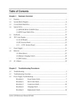 6
6 -
 7
7 -
8
-
9
-
10
-
11
-
12
-
13
-
14
-
15
-
16
-
17
-
18
-
19
-
20
-
21
-
22
-
23
-
24
-
25
-
26
-
27
-
28
-
29
-
30
-
31
-
32
-
33
-
34
-
35
-
36
-
37
-
38
-
39
-
40
-
41
-
42
-
43
-
44
-
45
-
46
-
47
-
48
-
49
-
50
-
51
-
52
-
53
-
54
-
55
-
56
-
57
-
58
-
59
-
60
-
61
-
62
-
63
-
64
-
65
-
66
-
67
-
68
-
69
-
70
-
71
-
72
-
73
-
74
-
75
-
76
-
77
-
78
-
79
-
80
-
81
-
82
-
83
-
84
-
85
-
86
-
87
-
88
-
89
-
90
-
91
-
92
-
93
-
94
-
95
-
96
-
97
-
98
-
99
-
100
-
101
-
102
-
103
-
104
-
105
-
106
-
107
-
108
-
109
-
110
-
111
-
112
-
113
-
114
-
115
-
116
-
117
-
118
-
119
-
120
-
121
-
122
-
123
-
124
-
125
-
126
-
127
-
128
-
129
-
130
-
131
-
132
-
133
-
134
-
135
-
136
-
137
-
138
-
139
-
140
-
141
-
142
-
143
-
144
-
145
-
146
-
147
-
148
-
149
-
150
-
151
-
152
-
153
-
154
-
155
-
156
-
157
-
158
-
159
-
160
-
161
-
162
-
163
-
164
-
165
-
166
-
167
-
168
-
169
-
170
-
171
-
172
-
173
-
174
-
175
-
176
-
177
-
178
-
179
-
180
-
181
-
182
-
183
-
184
-
185
-
186
-
187
-
188
-
189
-
190
-
191
-
192
-
193
-
194
-
195
-
196
-
197
-
198
-
199
-
200
-
201
-
202
-
203
-
204
-
205
-
206
-
207
-
208
-
209
-
210
-
211
-
212
-
213
-
214
-
215
-
216
-
217
-
218
-
219
-
220
-
221
-
222
-
223
-
224
-
225
-
226
-
227
-
228
-
229
-
230
-
231
-
232
-
233
-
234
-
235
-
236
-
237
-
238
-
239
-
240
-
241
-
242
-
243
-
244
-
245
-
246
-
247
-
248
-
249
-
250
-
251
-
252
-
253
-
254
-
255
-
256
-
257
-
258
-
259
-
260
-
261
-
262
-
263
 |
 |

Satellite A300
Maintenance Manual (960-Q08)
Toshiba Personal Computer
Satellite A300
Maintenance Manual
TOSHIBA CORPORATION
File Number 960-Q08