Toshiba Satellite A300 Maintenance Manual - Page 112
Procedure 3, Connector and Cable Check, If the connection is loose
 |
View all Toshiba Satellite A300 manuals
Add to My Manuals
Save this manual to your list of manuals |
Page 112 highlights
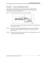
Troubleshooting Procedures Procedure 3 Connector and Cable Check LCD Module is connected to system board by an LCD/FL cable. FL inverter board is also connected to system board by an LCD/FL cable. And, fluorescent lamp is connected to FL inverter board by HV cable. Their cables may be disconnected from system board or FL inverter board. Disassemble the computer following the steps described in Chapter 4, Replacement Procedures. If the connection is loose, reconnect firmly and restart the computer. If the problem still occurs, go to Procedure 4. Satellite A300 Maintenance Manual (960-Q08) 36
-
 1
1 -
2
-
3
-
4
-
5
-
6
-
7
-
8
-
9
-
10
-
11
-
12
-
13
-
14
-
15
-
16
-
17
-
18
-
19
-
20
-
21
-
22
-
23
-
24
-
25
-
26
-
27
-
28
-
29
-
30
-
31
-
32
-
33
-
34
-
35
-
36
-
37
-
38
-
39
-
40
-
41
-
42
-
43
-
44
-
45
-
46
-
47
-
48
-
49
-
50
-
51
-
52
-
53
-
54
-
55
-
56
-
57
-
58
-
59
-
60
-
61
-
62
-
63
-
64
-
65
-
66
-
67
-
68
-
69
-
70
-
71
-
72
-
73
-
74
-
75
-
76
-
77
-
78
-
79
-
80
-
81
-
82
-
83
-
84
-
85
-
86
-
87
-
88
-
89
-
90
-
91
-
92
-
93
-
94
-
95
-
96
-
97
-
98
-
99
-
100
-
101
-
102
-
103
-
104
-
105
-
106
-
 107
107 -
 108
108 -
 109
109 -
 110
110 -
 111
111 -
 112
112 -
 113
113 -
 114
114 -
 115
115 -
 116
116 -
 117
117 -
118
-
119
-
120
-
121
-
122
-
123
-
124
-
125
-
126
-
127
-
128
-
129
-
130
-
131
-
132
-
133
-
134
-
135
-
136
-
137
-
138
-
139
-
140
-
141
-
142
-
143
-
144
-
145
-
146
-
147
-
148
-
149
-
150
-
151
-
152
-
153
-
154
-
155
-
156
-
157
-
158
-
159
-
160
-
161
-
162
-
163
-
164
-
165
-
166
-
167
-
168
-
169
-
170
-
171
-
172
-
173
-
174
-
175
-
176
-
177
-
178
-
179
-
180
-
181
-
182
-
183
-
184
-
185
-
186
-
187
-
188
-
189
-
190
-
191
-
192
-
193
-
194
-
195
-
196
-
197
-
198
-
199
-
200
-
201
-
202
-
203
-
204
-
205
-
206
-
207
-
208
-
209
-
210
-
211
-
212
-
213
-
214
-
215
-
216
-
217
-
218
-
219
-
220
-
221
-
222
-
223
-
224
-
225
-
226
-
227
-
228
-
229
-
230
-
231
-
232
-
233
-
234
-
235
-
236
-
237
-
238
-
239
-
240
-
241
-
242
-
243
-
244
-
245
-
246
-
247
-
248
-
249
-
250
-
251
-
252
-
253
-
254
-
255
-
256
-
257
-
258
-
259
-
260
-
261
-
262
-
263
 |
 |

Troubleshooting Procedures
Procedure 3
Connector and Cable Check
LCD Module is connected to system board by an LCD/FL cable. FL inverter board is also
connected to system board by an LCD/FL cable. And, fluorescent lamp is connected to FL
inverter board by HV cable. Their cables may be disconnected from system board or FL
inverter board. Disassemble the computer following the steps described in Chapter 4,
Replacement Procedures
.
If the connection is loose, reconnect firmly and restart the computer. If the problem still
occurs, go to Procedure 4.
36
Satellite A300
Maintenance Manual (960-Q08)