Toshiba Satellite A300 Maintenance Manual - Page 163
Installing the cover assembly, cover assembly, touch pad flat cable, screws
 |
View all Toshiba Satellite A300 manuals
Add to My Manuals
Save this manual to your list of manuals |
Page 163 highlights
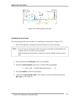
Replacement Procedures Installing the cover assembly The following describes the procedure for installing the cover assembly (See Figure 4-19 to 4-21). 1. Install the cover assembly to the base assembly. NOTE: Be careful not to catch the cables between cover assembly and base assembly. 2. Connect the touch pad flat cable to the connector on the system board. 3. Secure the cover assembly with the following screws from the back and bottom of computer. • M2.0×8.0 FLAT BIND screw Back x9 • M2.5×6.5 FLAT BIND screw Back x9 4. Disassemble the cable from cable-drain while taking the antenna cable to PCB hole. Satellite A300 Maintenance Manual(960-Q08) 4-32
-
 1
1 -
2
-
3
-
4
-
5
-
6
-
7
-
8
-
9
-
10
-
11
-
12
-
13
-
14
-
15
-
16
-
17
-
18
-
19
-
20
-
21
-
22
-
23
-
24
-
25
-
26
-
27
-
28
-
29
-
30
-
31
-
32
-
33
-
34
-
35
-
36
-
37
-
38
-
39
-
40
-
41
-
42
-
43
-
44
-
45
-
46
-
47
-
48
-
49
-
50
-
51
-
52
-
53
-
54
-
55
-
56
-
57
-
58
-
59
-
60
-
61
-
62
-
63
-
64
-
65
-
66
-
67
-
68
-
69
-
70
-
71
-
72
-
73
-
74
-
75
-
76
-
77
-
78
-
79
-
80
-
81
-
82
-
83
-
84
-
85
-
86
-
87
-
88
-
89
-
90
-
91
-
92
-
93
-
94
-
95
-
96
-
97
-
98
-
99
-
100
-
101
-
102
-
103
-
104
-
105
-
106
-
107
-
108
-
109
-
110
-
111
-
112
-
113
-
114
-
115
-
116
-
117
-
118
-
119
-
120
-
121
-
122
-
123
-
124
-
125
-
126
-
127
-
128
-
129
-
130
-
131
-
132
-
133
-
134
-
135
-
136
-
137
-
138
-
139
-
140
-
141
-
142
-
143
-
144
-
145
-
146
-
147
-
148
-
149
-
150
-
151
-
152
-
153
-
154
-
155
-
156
-
157
-
 158
158 -
 159
159 -
 160
160 -
 161
161 -
 162
162 -
 163
163 -
 164
164 -
 165
165 -
 166
166 -
 167
167 -
 168
168 -
169
-
170
-
171
-
172
-
173
-
174
-
175
-
176
-
177
-
178
-
179
-
180
-
181
-
182
-
183
-
184
-
185
-
186
-
187
-
188
-
189
-
190
-
191
-
192
-
193
-
194
-
195
-
196
-
197
-
198
-
199
-
200
-
201
-
202
-
203
-
204
-
205
-
206
-
207
-
208
-
209
-
210
-
211
-
212
-
213
-
214
-
215
-
216
-
217
-
218
-
219
-
220
-
221
-
222
-
223
-
224
-
225
-
226
-
227
-
228
-
229
-
230
-
231
-
232
-
233
-
234
-
235
-
236
-
237
-
238
-
239
-
240
-
241
-
242
-
243
-
244
-
245
-
246
-
247
-
248
-
249
-
250
-
251
-
252
-
253
-
254
-
255
-
256
-
257
-
258
-
259
-
260
-
261
-
262
-
263
 |
 |

Replacement Procedures
Satellite A300
Maintenance Manual(960-Q08)
4-32
Installing the cover assembly
The following describes the procedure for installing the cover assembly (See Figure 4-19 to
4-21).
1.
Install the
cover assembly
to the base assembly.
NOTE
:
Be careful not to catch the cables between cover assembly and base assembly.
2.
Connect the
touch pad flat cable
to the connector on the system board.
3.
Secure the cover assembly with the following
screws
from the back and bottom of
computer.
•
M2.0
×
8.0
FLAT BIND screw
Back
x9
•
M2.5
×
6.5
FLAT BIND screw
Back
x9
4.
Disassemble the cable from cable-drain while taking the antenna cable to PCB hole.