Yamaha CVP-405 Owner's Manual - Page 209
Voltage Selector, Fix A., Connect the pedal cord., Set the voltage selector and connect the power - reviews
 |
View all Yamaha CVP-405 manuals
Add to My Manuals
Save this manual to your list of manuals |
Page 209 highlights
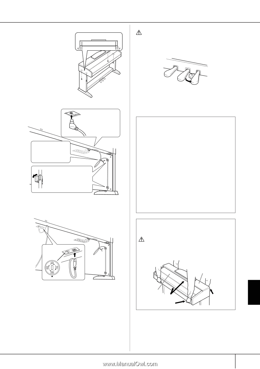
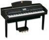
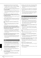
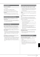
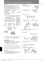
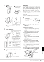
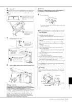
5 Fix A. 1 Center A to produce equal clearance on the left and right sides. 2 Use 6 ✕ 16 mm short screws to secure A from the front. A A WARNING An improper voltage setting can cause serious damage to the Clavinova or result in improper operation. 8 Set the adjuster. 6 Connect the pedal cord. 1 Insert the pedal cord plug to the pedal connector from the front. 3 Use a vinyl tie to take up any slack in the pedal cord. 2 Attach the cord holders to D as shown, then clip D the cord into the holders. 7 Set the voltage selector and connect the power cord. Rotate the adjuster until it comes in firm contact with the floor surface. ■ After completing the assembly, please check the following. • Are there any parts left over? → Review the assembly procedure and correct any errors. • Is the Clavinova clear of doors and other movable fixtures? → Move the Clavinova to an appropriate location. • Does the Clavinova make a rattling noise when you shake it? → Tighten all screws. • Does the pedal box rattle or give way when you step on the pedals? → Turn the adjuster so that it is set firmly against the floor. • Are the pedal and power cords inserted securely into the sockets? → Check the connection. • If the main unit creaks or is otherwise unsteady when you play on the keyboard, refer to the assembly diagrams and retighten all screws. When moving the instrument after assembly, always hold the bottom of the main unit. CAUTION Do not hold the key cover or top portion. Improper handling can result in damage to the instrument or personal injury. Voltage Selector Before connecting the AC power cord, check the setting of the voltage selector which is provided in some areas. To set the selector for 110V, 127V, 220V or 240V main voltages, use a "minus" screwdriver to rotate the selector dial so that the correct voltage for your region appears next to the pointer on the panel. The voltage selector is set at 240V when the unit is initially shipped. After the proper voltage has been selected, connect the AC power cord to the AC INLET and an AC wall outlet. A plug adaptor may be also provided in some areas to match the pin configuration of the AC wall outlets in your area. Key cover Do not hold here. Hold here. Top portion Do not hold here. Appendix CVP-405/403/401 Owner's Manual 209
-
 1
1 -
2
-
3
-
4
-
5
-
6
-
7
-
8
-
9
-
10
-
11
-
12
-
13
-
14
-
15
-
16
-
17
-
18
-
19
-
20
-
21
-
22
-
23
-
24
-
25
-
26
-
27
-
28
-
29
-
30
-
31
-
32
-
33
-
34
-
35
-
36
-
37
-
38
-
39
-
40
-
41
-
42
-
43
-
44
-
45
-
46
-
47
-
48
-
49
-
50
-
51
-
52
-
53
-
54
-
55
-
56
-
57
-
58
-
59
-
60
-
61
-
62
-
63
-
64
-
65
-
66
-
67
-
68
-
69
-
70
-
71
-
72
-
73
-
74
-
75
-
76
-
77
-
78
-
79
-
80
-
81
-
82
-
83
-
84
-
85
-
86
-
87
-
88
-
89
-
90
-
91
-
92
-
93
-
94
-
95
-
96
-
97
-
98
-
99
-
100
-
101
-
102
-
103
-
104
-
105
-
106
-
107
-
108
-
109
-
110
-
111
-
112
-
113
-
114
-
115
-
116
-
117
-
118
-
119
-
120
-
121
-
122
-
123
-
124
-
125
-
126
-
127
-
128
-
129
-
130
-
131
-
132
-
133
-
134
-
135
-
136
-
137
-
138
-
139
-
140
-
141
-
142
-
143
-
144
-
145
-
146
-
147
-
148
-
149
-
150
-
151
-
152
-
153
-
154
-
155
-
156
-
157
-
158
-
159
-
160
-
161
-
162
-
163
-
164
-
165
-
166
-
167
-
168
-
169
-
170
-
171
-
172
-
173
-
174
-
175
-
176
-
177
-
178
-
179
-
180
-
181
-
182
-
183
-
184
-
185
-
186
-
187
-
188
-
189
-
190
-
191
-
192
-
193
-
194
-
195
-
196
-
197
-
198
-
199
-
200
-
201
-
202
-
203
-
 204
204 -
 205
205 -
 206
206 -
 207
207 -
 208
208 -
 209
209 -
 210
210 -
 211
211 -
 212
212 -
 213
213 -
 214
214 -
215
-
216
-
217
-
218
-
219
-
220
-
221
-
222
-
223
-
224
-
225
-
226
 |
 |