ZyXEL VSG1432-B101 User Guide - Page 90
Introduction to IEEE 802.1Q Tagged VLAN
 |
View all ZyXEL VSG1432-B101 manuals
Add to My Manuals
Save this manual to your list of manuals |
Page 90 highlights
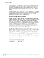
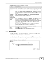
Chapter 6 Broadband In Multi-Tenant Unit (MTU) applications, VLAN is vital in providing isolation and security among the subscribers. When properly configured, VLAN prevents one subscriber from accessing the network resources of another on the same LAN, thus a user will not see the printers and hard disks of another user in the same building. VLAN also increases network performance by limiting broadcasts to a smaller and more manageable logical broadcast domain. In traditional switched environments, all broadcast packets go to each and every individual port. With VLAN, all broadcasts are confined to a specific broadcast domain. Introduction to IEEE 802.1Q Tagged VLAN A tagged VLAN uses an explicit tag (VLAN ID) in the MAC header to identify the VLAN membership of a frame across bridges - they are not confined to the switch on which they were created. The VLANs can be created statically by hand or dynamically through GVRP. The VLAN ID associates a frame with a specific VLAN and provides the information that switches need to process the frame across the network. A tagged frame is four bytes longer than an untagged frame and contains two bytes of TPID (Tag Protocol Identifier), residing within the type/ length field of the Ethernet frame) and two bytes of TCI (Tag Control Information), starts after the source address field of the Ethernet frame). The CFI (Canonical Format Indicator) is a single-bit flag, always set to zero for Ethernet switches. If a frame received at an Ethernet port has a CFI set to 1, then that frame should not be forwarded as it is to an untagged port. The remaining twelve bits define the VLAN ID, giving a possible maximum number of 4,096 VLANs. Note that user priority and VLAN ID are independent of each other. A frame with VID (VLAN Identifier) of null (0) is called a priority frame, meaning that only the priority level is significant and the default VID of the ingress port is given as the VID of the frame. Of the 4096 possible VIDs, a VID of 0 is used to identify priority frames and value 4095 (FFF) is reserved, so the maximum possible VLAN configurations are 4,094. TPID User Priority 2 Bytes 3 Bits CFI VLAN ID 1 Bit 12 Bits 90 VSG1432-B101 Series User's Guide
-
 1
1 -
2
-
3
-
4
-
5
-
6
-
7
-
8
-
9
-
10
-
11
-
12
-
13
-
14
-
15
-
16
-
17
-
18
-
19
-
20
-
21
-
22
-
23
-
24
-
25
-
26
-
27
-
28
-
29
-
30
-
31
-
32
-
33
-
34
-
35
-
36
-
37
-
38
-
39
-
40
-
41
-
42
-
43
-
44
-
45
-
46
-
47
-
48
-
49
-
50
-
51
-
52
-
53
-
54
-
55
-
56
-
57
-
58
-
59
-
60
-
61
-
62
-
63
-
64
-
65
-
66
-
67
-
68
-
69
-
70
-
71
-
72
-
73
-
74
-
75
-
76
-
77
-
78
-
79
-
80
-
81
-
82
-
83
-
84
-
 85
85 -
 86
86 -
 87
87 -
 88
88 -
 89
89 -
 90
90 -
 91
91 -
 92
92 -
 93
93 -
 94
94 -
 95
95 -
96
-
97
-
98
-
99
-
100
-
101
-
102
-
103
-
104
-
105
-
106
-
107
-
108
-
109
-
110
-
111
-
112
-
113
-
114
-
115
-
116
-
117
-
118
-
119
-
120
-
121
-
122
-
123
-
124
-
125
-
126
-
127
-
128
-
129
-
130
-
131
-
132
-
133
-
134
-
135
-
136
-
137
-
138
-
139
-
140
-
141
-
142
-
143
-
144
-
145
-
146
-
147
-
148
-
149
-
150
-
151
-
152
-
153
-
154
-
155
-
156
-
157
-
158
-
159
-
160
-
161
-
162
-
163
-
164
-
165
-
166
-
167
-
168
-
169
-
170
-
171
-
172
-
173
-
174
-
175
-
176
-
177
-
178
-
179
-
180
-
181
-
182
-
183
-
184
-
185
-
186
-
187
-
188
-
189
-
190
-
191
-
192
-
193
-
194
-
195
-
196
-
197
-
198
-
199
-
200
-
201
-
202
-
203
-
204
-
205
-
206
-
207
-
208
-
209
-
210
-
211
-
212
-
213
-
214
-
215
-
216
-
217
-
218
-
219
-
220
-
221
-
222
-
223
-
224
-
225
-
226
-
227
-
228
-
229
-
230
-
231
-
232
-
233
-
234
-
235
-
236
-
237
-
238
-
239
-
240
-
241
-
242
-
243
-
244
-
245
-
246
-
247
-
248
-
249
-
250
-
251
-
252
-
253
-
254
-
255
-
256
-
257
-
258
-
259
-
260
-
261
-
262
-
263
-
264
-
265
-
266
-
267
-
268
-
269
-
270
-
271
-
272
-
273
-
274
-
275
-
276
-
277
-
278
-
279
-
280
-
281
-
282
-
283
-
284
-
285
-
286
-
287
-
288
-
289
-
290
-
291
-
292
-
293
-
294
-
295
-
296
-
297
-
298
-
299
-
300
-
301
-
302
-
303
-
304
-
305
-
306
-
307
-
308
-
309
-
310
-
311
-
312
-
313
-
314
-
315
-
316
-
317
-
318
-
319
-
320
-
321
-
322
-
323
-
324
-
325
-
326
-
327
-
328
-
329
-
330
-
331
-
332
-
333
-
334
-
335
-
336
-
337
-
338
-
339
-
340
-
341
-
342
-
343
-
344
-
345
-
346
-
347
-
348
-
349
-
350
-
351
-
352
-
353
-
354
-
355
-
356
-
357
-
358
-
359
-
360
-
361
-
362
-
363
-
364
-
365
-
366
-
367
-
368
-
369
-
370
-
371
-
372
-
373
-
374
-
375
-
376
-
377
-
378
-
379
-
380
-
381
-
382
-
383
-
384
-
385
-
386
-
387
-
388
-
389
-
390
-
391
-
392
-
393
-
394
-
395
-
396
-
397
-
398
-
399
-
400
-
401
-
402
-
403
-
404
-
405
-
406
-
407
-
408
 |
 |
