3Com 3C886 User Guide - Page 29
Back Panel Connector Description, Installing the 56K LAN Modem, Before You Begin, Back Panel Connector
 |
UPC - 662705169279
View all 3Com 3C886 manuals
Add to My Manuals
Save this manual to your list of manuals |
Page 29 highlights
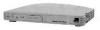
Installing the 56K LAN Modem 29 Table 4 Front Panel LED Indicator Definitions (continued) LED Color Coll Amber Ports 1-4 Green Description Ethernet Collision Status. Flashes amber when some collisions are taking place on the Ethernet LAN. Off indicates that no collisions are taking place on the Ethernet LAN. Ethernet LAN Port Status. On indicates that the unit detects the Ethernet link integrity signal from an attached computer and operation is normal. Flashes when the LAN Modem receives data on the associated port. Off indicates the unit does not detect the Ethernet link integrity signal. The Ethernet cable may not be properly connected or the cable may be the wrong polarity. Back Panel Connector The back panel provides the following components. Description 10-18 VDC 0.8 A MAX Power Connector RESET LINE PHONE 4 3 LAN 2 1 Reset Button Telephone Line Four Ethernet Analog 10BASE-T Connectors Device Figure 10 56K LAN Modem Back Panel From left to right the back panel consists of the following. s Power: Connect the power module cable to this port. s Reset: Press this button to re-initialize the unit. s Line: Connect the provided RJ-11 analog line from the wall outlet to this port. s Phone: Connect an external analog device, such as a telephone or fax machine, to this port. s Four 10BASE-T Ethernet Ports: Connect the computers on your LAN, or an external hub, to these ports. Installing the 56K LAN Modem This section describes how to do the following. s Install the analog cable s Connect to a 10BASE-T Ethernet LAN s Install analog equipment s Install the power cable Before You Begin Before you begin, you will need the following in addition to the 56K LAN Modem: s RJ-11 (6-pin) to RJ-11 (6-pin) telephone cable which was provided in your modem package.
-
 1
1 -
2
-
3
-
4
-
5
-
6
-
7
-
8
-
9
-
10
-
11
-
12
-
13
-
14
-
15
-
16
-
17
-
18
-
19
-
20
-
21
-
22
-
23
-
 24
24 -
 25
25 -
 26
26 -
 27
27 -
 28
28 -
 29
29 -
 30
30 -
 31
31 -
 32
32 -
 33
33 -
 34
34 -
35
-
36
-
37
-
38
-
39
-
40
-
41
-
42
-
43
-
44
-
45
-
46
-
47
-
48
-
49
-
50
-
51
-
52
-
53
-
54
-
55
-
56
-
57
-
58
-
59
-
60
-
61
-
62
-
63
-
64
-
65
-
66
-
67
-
68
-
69
-
70
-
71
-
72
-
73
-
74
-
75
-
76
-
77
-
78
-
79
-
80
-
81
-
82
-
83
-
84
-
85
-
86
-
87
-
88
-
89
-
90
-
91
-
92
-
93
-
94
-
95
-
96
-
97
-
98
-
99
-
100
-
101
-
102
-
103
-
104
-
105
-
106
-
107
-
108
-
109
-
110
-
111
-
112
-
113
-
114
-
115
-
116
 |
 |
