3Ware 9650SE-8LPML-SGL Installation Guide - Page 20
Step 1 (9650SE-2LP). Connect the Cables to the Controller, orientation and installation
 |
UPC - 693494600087
View all 3Ware 9650SE-8LPML-SGL manuals
Add to My Manuals
Save this manual to your list of manuals |
Page 20 highlights
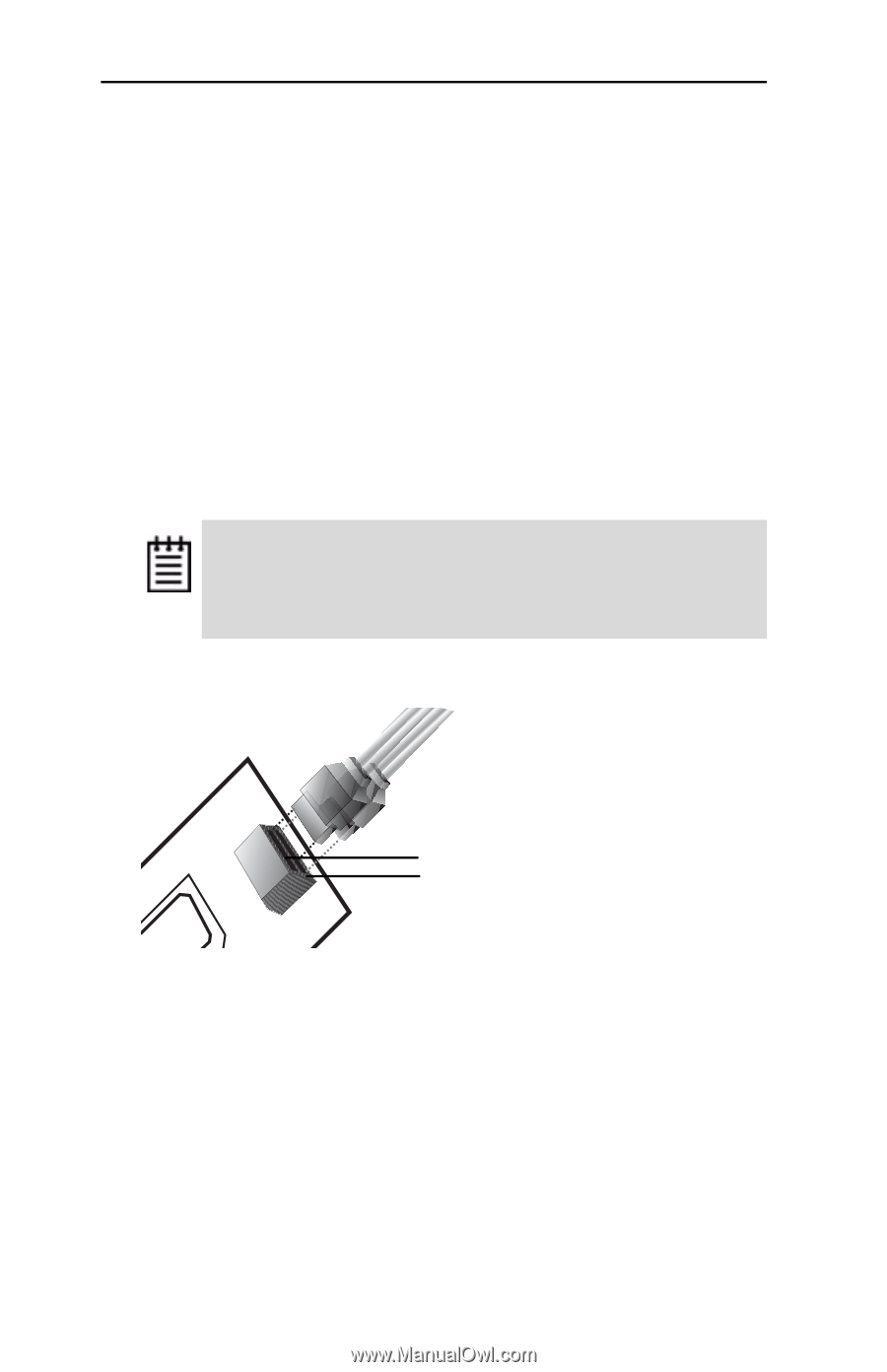
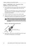
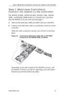
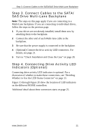
Chapter 2. Installing Your 3ware RAID Controller Step 1 (9650SE-2LP). Connect the Cables to the Controller 1 For the 9650SE-2LP, take out the SATA cables provided with the controller. (For other 9650SE models, turn to the next page.) One edge of each SATA cable connector is keyed so that it can only be inserted in one direction. This helps to ensure proper orientation and installation 2 Decide to which port you want to connect the first cable. 3 Align the cable connector with the connector on the controller, matching the slotted key and carefully mate the connectors. Note: The connectors on the end of the serial controller and the drive are susceptible to damage from excessive bending. Be careful not to insert or remove the SATA cable connector at an angle. Figure 11. SATA Cables Being Inserted Into Port Port 0 is on top. Port 1 is on the bottom 4 Repeat steps 2 and 3 for the second SATA cable. (You connect one cable for each hard drive you will attach.) 16 3ware 9650SE Serial ATA RAID Controller Installation Guide
-
 1
1 -
2
-
3
-
4
-
5
-
6
-
7
-
8
-
9
-
10
-
11
-
12
-
13
-
14
-
 15
15 -
 16
16 -
 17
17 -
 18
18 -
 19
19 -
 20
20 -
 21
21 -
 22
22 -
 23
23 -
 24
24 -
 25
25 -
26
-
27
-
28
-
29
-
30
-
31
-
32
-
33
-
34
-
35
-
36
-
37
-
38
-
39
-
40
-
41
-
42
-
43
-
44
-
45
 |
 |