3Ware 9650SE-8LPML-SGL Installation Guide - Page 26
Port 3ware 9650SE-2LP Serial ATA RAID Controller
 |
UPC - 693494600087
View all 3Ware 9650SE-8LPML-SGL manuals
Add to My Manuals
Save this manual to your list of manuals |
Page 26 highlights
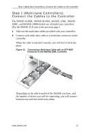
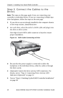
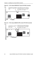
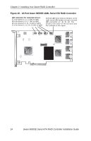
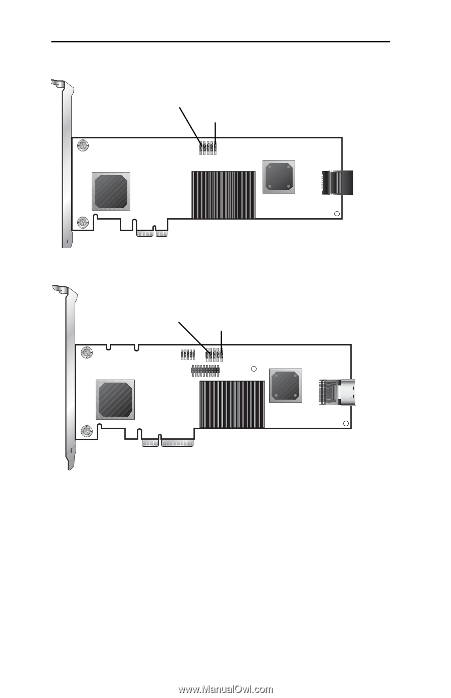
Chapter 2. Installing Your 3ware RAID Controller Figure 15. 2-Port 3ware 9650SE-2LP Serial ATA RAID Controller LED indicators for individual drives on J7: 0 and 1 (left to right) Overall LED drive status indicator: the last two pins of J7. The anode is the lower of the two pins and the cathode is the upper. Figure 16. 4-Port 3ware 9650SE-4LPML Serial ATA RAID Controller LED indicators for individual drives on J7: 0, 1, 2, 3 (left to right) Overall LED drive status indicator: the last two pins of J7. The anode is the lower of the two pins and the cathode is the upper. 22 3ware 9650SE Serial ATA RAID Controller Installation Guide
-
 1
1 -
2
-
3
-
4
-
5
-
6
-
7
-
8
-
9
-
10
-
11
-
12
-
13
-
14
-
15
-
16
-
17
-
18
-
19
-
20
-
 21
21 -
 22
22 -
 23
23 -
 24
24 -
 25
25 -
 26
26 -
 27
27 -
 28
28 -
 29
29 -
 30
30 -
 31
31 -
32
-
33
-
34
-
35
-
36
-
37
-
38
-
39
-
40
-
41
-
42
-
43
-
44
-
45
 |
 |
Chapter 2. Installing Your 3ware RAID Controller
22
3ware 9650SE Serial ATA RAID Controller Installation Guide
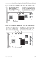
Figure 15. 2-Port 3ware 9650SE-2LP Serial ATA RAID Controller
Figure 16. 4-Port 3ware 9650SE-4LPML Serial ATA RAID Controller
LED indicators for individual
drives on J7: 0 and 1 (left to
right)
Overall LED drive status indicator:
the last two pins of J7. The anode
is the lower of the two pins and
the cathode is the upper.
LED indicators for individual
drives on J7: 0, 1, 2, 3
(left to right)
Overall LED drive status indicator:
the last two pins of J7. The anode
is the lower of the two pins and
the cathode is the upper.