3Ware 9650SE-8LPML-SGL Installation Guide - Page 32
Step 5. Finishing Up the RAID Controller Installation, Check Installation and Close the Case
 |
UPC - 693494600087
View all 3Ware 9650SE-8LPML-SGL manuals
Add to My Manuals
Save this manual to your list of manuals |
Page 32 highlights
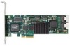
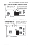
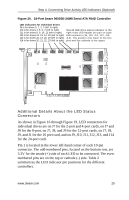
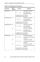
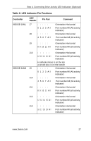
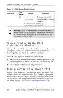
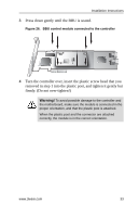
Chapter 2. Installing Your 3ware RAID Controller Table 2: LED Indicator Pin Positions Controller LED Header Pin Pair Comment J14 : : : : : Orientation Horizontal 20 21 22 23 All Port number/All (all activity indicator) k-cathode-minus is on the top a-anode-plus is on the bottom Warning: If using a chassis that has a common or shared LED ground, be sure to only connect LED cables to the anode pins on the controller. Do not connect any common ground to any cathode pins on the controller. Step 5. Finishing Up the RAID Controller Installation After you have installed the controller in the computer and attached appropriate cables to the controller and drives, complete the following steps to complete the hardware installation. Check Installation and Close the Case 1 Verify that the cables do not interfere with the operation of any other components in the case or block the flow of cooling air. 2 Close the case and reconnect the power cables. Step 6. Configure Your RAID Arrays Turn to "First Time RAID Configuration" and "Configuring Units" in 3ware Serial ATA RAID Controller User Guide for information about configuring RAID arrays. The user guide is included on the 3ware CD that came with your controller. It is also available from the 3ware website at http://3ware.com/support/userdocs.asp. 28 3ware 9650SE Serial ATA RAID Controller Installation Guide
-
 1
1 -
2
-
3
-
4
-
5
-
6
-
7
-
8
-
9
-
10
-
11
-
12
-
13
-
14
-
15
-
16
-
17
-
18
-
19
-
20
-
21
-
22
-
23
-
24
-
25
-
26
-
 27
27 -
 28
28 -
 29
29 -
 30
30 -
 31
31 -
 32
32 -
 33
33 -
 34
34 -
 35
35 -
 36
36 -
 37
37 -
38
-
39
-
40
-
41
-
42
-
43
-
44
-
45
 |
 |