3Ware 9650SE-8LPML-SGL Installation Guide - Page 34
Tools and equipment required, Installation Overview, Battery Backup Unit BBU and battery
 |
UPC - 693494600087
View all 3Ware 9650SE-8LPML-SGL manuals
Add to My Manuals
Save this manual to your list of manuals |
Page 34 highlights
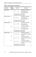
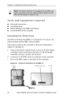
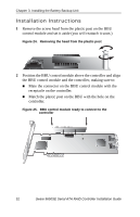
Chapter 3. Installing the Battery Backup Unit Note: The battery will drain if it is plugged into the BBU and there is no power to the unit. Wait to plug the battery into the BBU until the system is ready for use. Tools and equipment required „ Slot-head screwdriver „ Grounding strap „ Battery Backup Unit (BBU) and battery „ 3ware 9650SE series controller Installation Overview The Battery Backup Unit (BBU) is comprised of two pieces: the battery module and the BBU control module. These pieces attach to the controller at the points illustrated in Figures 21 through 23: a Clips on the battery module match to slots on the half-height controllers (4-port and 8-port) and holes on the full-height controllers (12-port, 16-port, and 24-port). b Connector on the BBU mates to receptacle on the controller. c Post on the BBU mates to post hole on the controller. Figure 21. Points of connection on the BBU a) Clips b) BBU connector c) Post 30 3ware 9650SE Serial ATA RAID Controller Installation Guide
-
 1
1 -
2
-
3
-
4
-
5
-
6
-
7
-
8
-
9
-
10
-
11
-
12
-
13
-
14
-
15
-
16
-
17
-
18
-
19
-
20
-
21
-
22
-
23
-
24
-
25
-
26
-
27
-
28
-
 29
29 -
 30
30 -
 31
31 -
 32
32 -
 33
33 -
 34
34 -
 35
35 -
 36
36 -
 37
37 -
 38
38 -
 39
39 -
40
-
41
-
42
-
43
-
44
-
45
 |
 |