3Ware 9650SE-8LPML-SGL Installation Guide - Page 24
Step 3. Connect the Cables to the Drives - 21
 |
UPC - 693494600087
View all 3Ware 9650SE-8LPML-SGL manuals
Add to My Manuals
Save this manual to your list of manuals |
Page 24 highlights
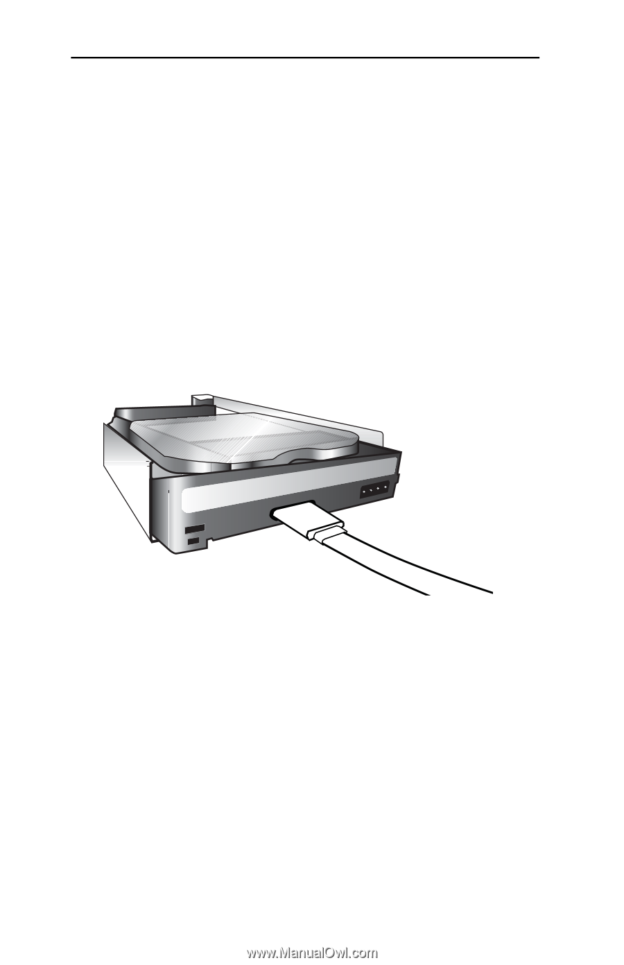
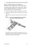
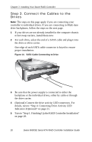
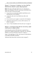
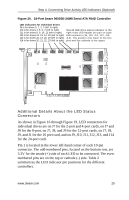
Chapter 2. Installing Your 3ware RAID Controller Step 3. Connect the Cables to the Drives Note: The steps on this page apply if you are connecting your controller to individual drives. If you are connecting to Multi-lane drive backplanes, follow the steps on the next page. 1 If your drives are not already installed in the computer chassis or hot swap carriers, install them now. 2 For each drive, select the end of a SATA cable and plug it into the drive or drive carrier. One edge of each SATA cable connector is keyed to ensure proper installation. Figure 14. SATA Cable Connecting to Drive 3 Be sure that the power supply is connected to either the backplane or the individual drives, either by cable or through the drive carrier. 4 (Optional) Connect the drive activity LED connectors. For details, turn to "Step 4. Connecting Drive Activity LED Indicators (Optional)" on page 21. 5 Turn to "Step 5. Finishing Up the RAID Controller Installation" on page 28. 20 3ware 9650SE Serial ATA RAID Controller Installation Guide
-
 1
1 -
2
-
3
-
4
-
5
-
6
-
7
-
8
-
9
-
10
-
11
-
12
-
13
-
14
-
15
-
16
-
17
-
18
-
 19
19 -
 20
20 -
 21
21 -
 22
22 -
 23
23 -
 24
24 -
 25
25 -
 26
26 -
 27
27 -
 28
28 -
 29
29 -
30
-
31
-
32
-
33
-
34
-
35
-
36
-
37
-
38
-
39
-
40
-
41
-
42
-
43
-
44
-
45
 |
 |