3Ware 9650SE-8LPML-SGL Installation Guide - Page 29
Additional Details About the LED Status Connectors
 |
UPC - 693494600087
View all 3Ware 9650SE-8LPML-SGL manuals
Add to My Manuals
Save this manual to your list of manuals |
Page 29 highlights
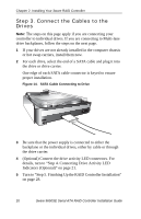
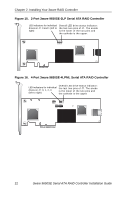
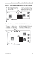
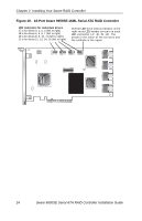
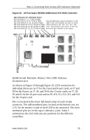
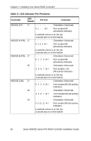
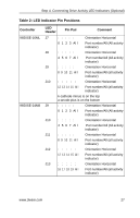
Step 4. Connecting Drive Activity LED Indicators (Optional) Figure 20. 24-Port 3ware 9650SE-24M8 Serial ATA RAID Controller LED indicators for individual drives J9 is for drives 0, 1, 2, 3 (left to right) J10 is for drives 4, 5, 6, 7 (left to right) Overall LED drive status indicator is the J11 is for drives 8, 9, 10, 11 (left to right) right-most LED header pin pair on each J12 is for drives 12, 13, 14, 15 (left to right) LED connector (J9, J10, J11, J12, J13, J13 is for drives 16, 17, 18, 19 (left to right) J14). The anode is the lower of the two J14 is for drives 20, 21, 22, 23 (left to right) pins and the cathode is the upper. Additional Details About the LED Status Connectors As shown in Figure 16 through Figure 19, LED connectors for individual drives are on J7 for the 2-port and 4-port cards, on J7 and J8 for the 8-port, on J7, J8, and J9 for the 12-port cards, on J7, J8, J9, and J1 for the 16 port card, and on J9, J10, J11, J12, J13, and J14 for the 24-port card. Pin 1 is located in the lower left-hand corner of each 10-pin connector. The odd-numbered pins, located on the bottom row, are 3.3V for the anode (+) side of each LED to be connected. The evennumbered pins are on the top or cathode (-) side. Table 2 summarizes the LED indicator pin positions for the different controllers. www.3ware.com 25
-
 1
1 -
2
-
3
-
4
-
5
-
6
-
7
-
8
-
9
-
10
-
11
-
12
-
13
-
14
-
15
-
16
-
17
-
18
-
19
-
20
-
21
-
22
-
23
-
 24
24 -
 25
25 -
 26
26 -
 27
27 -
 28
28 -
 29
29 -
 30
30 -
 31
31 -
 32
32 -
 33
33 -
 34
34 -
35
-
36
-
37
-
38
-
39
-
40
-
41
-
42
-
43
-
44
-
45
 |
 |
