3Ware 9650SE-8LPML-SGL Installation Guide - Page 25
Step 3. Connect Cables to the SATA/ SAS Drive Multi-Lane Backplane
 |
UPC - 693494600087
View all 3Ware 9650SE-8LPML-SGL manuals
Add to My Manuals
Save this manual to your list of manuals |
Page 25 highlights
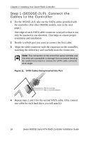
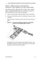
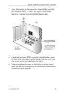
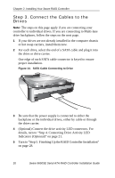
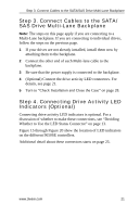
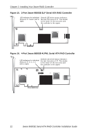
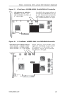
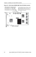
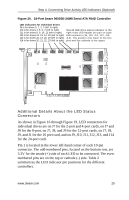
Step 3. Connect Cables to the SATA/SAS Drive Multi-Lane Backplane Step 3. Connect Cables to the SATA/ SAS Drive Multi-Lane Backplane Note: The steps on this page apply if you are connecting to a Multi-Lane backplane. If you are connecting to individual drives, follow the steps on the previous page. 1 If your drives are not already installed, install them now by attaching them to the backplane. 2 Connect the other end of each Multi-lane cable to the backplane. 3 Be sure that the power supply is connected to the backplane. 4 (Optional) Connect the drive activity LED connectors. For details, see page 21. 5 Turn to "Check Installation and Close the Case" on page 28. Step 4. Connecting Drive Activity LED Indicators (Optional) Connecting drive activity LED indicators is optional. For a discussion of whether to make these connections, see "Deciding Whether to Use the LED Status Connector" on page 13. Figure 15 through Figure 20 show the location of LED indicators on the different 9650SE controllers. Additional detail about these connectors starts on page 25. www.3ware.com 21
-
 1
1 -
2
-
3
-
4
-
5
-
6
-
7
-
8
-
9
-
10
-
11
-
12
-
13
-
14
-
15
-
16
-
17
-
18
-
19
-
 20
20 -
 21
21 -
 22
22 -
 23
23 -
 24
24 -
 25
25 -
 26
26 -
 27
27 -
 28
28 -
 29
29 -
 30
30 -
31
-
32
-
33
-
34
-
35
-
36
-
37
-
38
-
39
-
40
-
41
-
42
-
43
-
44
-
45
 |
 |