Acer Altos G710 Altos G710 User's Guide - Page 159
Pull the stands from the server, Remove the inner rails from the mounting rails by following
 |
View all Acer Altos G710 manuals
Add to My Manuals
Save this manual to your list of manuals |
Page 159 highlights
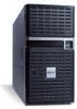
149 (3) Pull the stands from the server (3). 3 Remove the inner rails from the mounting rails by following the steps below: Note: The rack mount kit contains a bag of screws, two sets of side handles, rack brackets and mounting rails. The side handles are attached to the sides of the server. The rack brackets attach the mounting rails to the server. The mounting rails allow the server to slide in and out of the rackmount for maintenance purposes. Each mounting rail consists of: inner rail, middle slide, and fixed outer rail. The fixed outer piece is screwed onto the rack bracket with a M4 x L8 metal screw and nut, an inner rail is attached to the sides of the server with the #8-32 screws and an middle sliding piece controlled by a steel ball gearing movement. (1) Extend the inner rail from the mounting rail until the rail release latch clicks.
-
 1
1 -
2
-
3
-
4
-
5
-
6
-
7
-
8
-
9
-
10
-
11
-
12
-
13
-
14
-
15
-
16
-
17
-
18
-
19
-
20
-
21
-
22
-
23
-
24
-
25
-
26
-
27
-
28
-
29
-
30
-
31
-
32
-
33
-
34
-
35
-
36
-
37
-
38
-
39
-
40
-
41
-
42
-
43
-
44
-
45
-
46
-
47
-
48
-
49
-
50
-
51
-
52
-
53
-
54
-
55
-
56
-
57
-
58
-
59
-
60
-
61
-
62
-
63
-
64
-
65
-
66
-
67
-
68
-
69
-
70
-
71
-
72
-
73
-
74
-
75
-
76
-
77
-
78
-
79
-
80
-
81
-
82
-
83
-
84
-
85
-
86
-
87
-
88
-
89
-
90
-
91
-
92
-
93
-
94
-
95
-
96
-
97
-
98
-
99
-
100
-
101
-
102
-
103
-
104
-
105
-
106
-
107
-
108
-
109
-
110
-
111
-
112
-
113
-
114
-
115
-
116
-
117
-
118
-
119
-
120
-
121
-
122
-
123
-
124
-
125
-
126
-
127
-
128
-
129
-
130
-
131
-
132
-
133
-
134
-
135
-
136
-
137
-
138
-
139
-
140
-
141
-
142
-
143
-
144
-
145
-
146
-
147
-
148
-
149
-
150
-
151
-
152
-
153
-
 154
154 -
 155
155 -
 156
156 -
 157
157 -
 158
158 -
 159
159 -
 160
160 -
 161
161 -
 162
162 -
 163
163 -
 164
164 -
165
-
166
-
167
-
168
-
169
-
170
-
171
-
172
-
173
-
174
-
175
-
176
-
177
-
178
-
179
-
180
-
181
-
182
-
183
-
184
-
185
-
186
-
187
-
188
-
189
-
190
-
191
-
192
-
193
-
194
-
195
-
196
-
197
-
198
 |
 |
