Acer Altos G710 Altos G710 User's Guide - Page 19
Service ID indicator, Service ID button
 |
View all Acer Altos G710 manuals
Add to My Manuals
Save this manual to your list of manuals |
Page 19 highlights
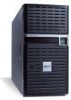
9 No. Icon 6 Component 5.25-inch drive bays 7 Power indicator 1 8 Hard disk activity indicator 1 9 System status indicator 1 10 LAN1 activity indicator 1 11 LAN2 activity indicator 1 12 Service ID indicator Description Two empty 5.25-inch drive bays allow installation of additional devices. Indicates AC power is present or system is turned on or off (green). Indicates the status of the system hard drive status. The indicator lights up green when the system is operating normally. When the a system fault is present, the indicator blinks or lights up amber. Indicates an active link on the LAN1 port (green). Indicates an active link on the LAN2 port (green). Indicates chassis ID status (blue). 13 Service ID button Illuminates LEDs on both the front and rear of the server, simplifying identification of the server in a rack from the rear. 14 Four-bay hot-plug Houses four hot-swap SCSI drives. HDD cage 15 HDD bay For additional storage options. Supports a four-bay hot-plug HDD cage. 16 USB ports Connects to USB devices. 17 Hot-plug HDD access Indicates the status of the hard indicator 2 drive. 18 Hot-plug HDD power Indicates drive activity (green). indicator 2
-
 1
1 -
2
-
3
-
4
-
5
-
6
-
7
-
8
-
9
-
10
-
11
-
12
-
13
-
 14
14 -
 15
15 -
 16
16 -
 17
17 -
 18
18 -
 19
19 -
 20
20 -
 21
21 -
 22
22 -
 23
23 -
 24
24 -
25
-
26
-
27
-
28
-
29
-
30
-
31
-
32
-
33
-
34
-
35
-
36
-
37
-
38
-
39
-
40
-
41
-
42
-
43
-
44
-
45
-
46
-
47
-
48
-
49
-
50
-
51
-
52
-
53
-
54
-
55
-
56
-
57
-
58
-
59
-
60
-
61
-
62
-
63
-
64
-
65
-
66
-
67
-
68
-
69
-
70
-
71
-
72
-
73
-
74
-
75
-
76
-
77
-
78
-
79
-
80
-
81
-
82
-
83
-
84
-
85
-
86
-
87
-
88
-
89
-
90
-
91
-
92
-
93
-
94
-
95
-
96
-
97
-
98
-
99
-
100
-
101
-
102
-
103
-
104
-
105
-
106
-
107
-
108
-
109
-
110
-
111
-
112
-
113
-
114
-
115
-
116
-
117
-
118
-
119
-
120
-
121
-
122
-
123
-
124
-
125
-
126
-
127
-
128
-
129
-
130
-
131
-
132
-
133
-
134
-
135
-
136
-
137
-
138
-
139
-
140
-
141
-
142
-
143
-
144
-
145
-
146
-
147
-
148
-
149
-
150
-
151
-
152
-
153
-
154
-
155
-
156
-
157
-
158
-
159
-
160
-
161
-
162
-
163
-
164
-
165
-
166
-
167
-
168
-
169
-
170
-
171
-
172
-
173
-
174
-
175
-
176
-
177
-
178
-
179
-
180
-
181
-
182
-
183
-
184
-
185
-
186
-
187
-
188
-
189
-
190
-
191
-
192
-
193
-
194
-
195
-
196
-
197
-
198
 |
 |
