Acer Altos G710 Altos G710 User's Guide - Page 68
Removing the heatsink and CPU, Place the heatsink upside
 |
View all Acer Altos G710 manuals
Add to My Manuals
Save this manual to your list of manuals |
Page 68 highlights
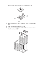
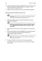
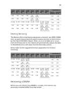
58 3 System upgrade 10 Connect the CPU fan cable to the CPU fan (0 or 1) connector on the mainboard. Refer to "Mainboard layout" on page 17 for the location of the CPU fan connector. 11 Observe the post-installation instructions described on page 40. Removing the heatsink and CPU Important: Before removing a CPU from the mainboard, make sure to create a backup file of all important data. 1 Observe the ESD precautions and pre-installation procedures described on page 39. Warning! The heatsink becomes very hot when the system is on. NEVER touch the heatsink with any metal or with your hands. 2 Loosen the four screws that hold the heatsink to the mainboard (1). 3 Pull out the heatsink from the CPU (2). Place the heatsink upside down on a flat surface to prevent thermal grease from contaminating other components. Note: Wipe off the thermal grease from both the heatsink and CPU using an alcohol pad. 4 To detach the CPU from its socket, follow the steps below: (1) Pull the CPU socket retainer lever to the fully open, upright position (1).
-
 1
1 -
2
-
3
-
4
-
5
-
6
-
7
-
8
-
9
-
10
-
11
-
12
-
13
-
14
-
15
-
16
-
17
-
18
-
19
-
20
-
21
-
22
-
23
-
24
-
25
-
26
-
27
-
28
-
29
-
30
-
31
-
32
-
33
-
34
-
35
-
36
-
37
-
38
-
39
-
40
-
41
-
42
-
43
-
44
-
45
-
46
-
47
-
48
-
49
-
50
-
51
-
52
-
53
-
54
-
55
-
56
-
57
-
58
-
59
-
60
-
61
-
62
-
 63
63 -
 64
64 -
 65
65 -
 66
66 -
 67
67 -
 68
68 -
 69
69 -
 70
70 -
 71
71 -
 72
72 -
 73
73 -
74
-
75
-
76
-
77
-
78
-
79
-
80
-
81
-
82
-
83
-
84
-
85
-
86
-
87
-
88
-
89
-
90
-
91
-
92
-
93
-
94
-
95
-
96
-
97
-
98
-
99
-
100
-
101
-
102
-
103
-
104
-
105
-
106
-
107
-
108
-
109
-
110
-
111
-
112
-
113
-
114
-
115
-
116
-
117
-
118
-
119
-
120
-
121
-
122
-
123
-
124
-
125
-
126
-
127
-
128
-
129
-
130
-
131
-
132
-
133
-
134
-
135
-
136
-
137
-
138
-
139
-
140
-
141
-
142
-
143
-
144
-
145
-
146
-
147
-
148
-
149
-
150
-
151
-
152
-
153
-
154
-
155
-
156
-
157
-
158
-
159
-
160
-
161
-
162
-
163
-
164
-
165
-
166
-
167
-
168
-
169
-
170
-
171
-
172
-
173
-
174
-
175
-
176
-
177
-
178
-
179
-
180
-
181
-
182
-
183
-
184
-
185
-
186
-
187
-
188
-
189
-
190
-
191
-
192
-
193
-
194
-
195
-
196
-
197
-
198
 |
 |
