Adaptec 1405 User Guide - Page 39
Connecting Drive LED Control Cables, Behavioral Pattern of Drive LED
 |
View all Adaptec 1405 manuals
Add to My Manuals
Save this manual to your list of manuals |
Page 39 highlights
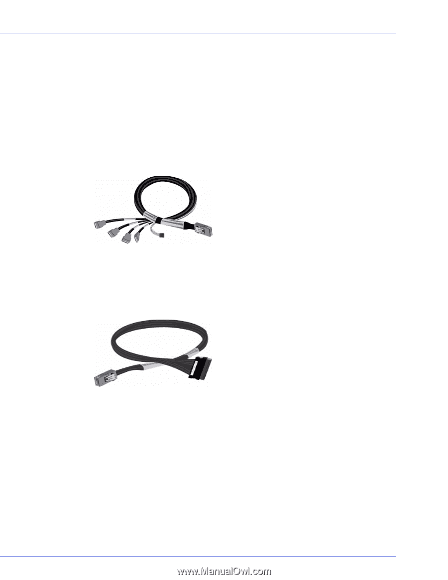
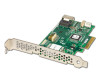
Chapter 8: Enclosure Management Support l 39 Connecting Drive LED Control Cables Drive LED Control Cables helps you to detect/verify the faulty drives and slots in the Backplane or Enclosure. Using an internal SATA fan-out cable, connect the controller to the SATA/SAS of the backplance. Ensure that the first data connector of the fan-out cable is connected to the port 0 of the backplane and rest of the other connectors respectively. Note that the port 0 starts at the bottom of the connector. Note: Depending on the jumper settings, the Backplane can be configured to use either I2C or SGPIO. Internal Mini SAS x4 (SFF-8087) to SATA fanout cable with sideband - connects controller to a maximum of four SATA devices or a backplane. Note: The sideband (SFF-8448) connector is used to connect with a managed backplane or enclosure. The four data connectors in the fan-out end must be connected to the SATA/SAS ports present in the enclosure. The sideband connector is connected to the I2C interface of backplane, and this helps in enabling the function of drive LEDs. Internal Mini SAS (SFF-8087) to SAS x4 (SFF-8484) - connects to SATA/SAS backplane Using Mini SAS (SFF-8087) cable, the SATA/SAS controller is connected to the Internal Enclosure or Backplane. This has a built-in I2C connector, which helps in enabling the function of drive LEDs. Behavioral Pattern of Drive LED ● Initialization of drives - If a SAS drive is present, the LED will blink continously till the I/O operation is initiated. If a SATA drive is present, the LED glows once and then stops. ● Read/Write operation in the disk -If a SAS drive is present, the LED will blink continously till the I/O operation is complete. If a SATA drive is present, the LED will glow till the I/O operation is complete. ● Faulty conditions - If you encounter any errors such as bad sectors or drive failure, the Fault LED will glow red untill the problem is rectified.
-
 1
1 -
2
-
3
-
4
-
5
-
6
-
7
-
8
-
9
-
10
-
11
-
12
-
13
-
14
-
15
-
16
-
17
-
18
-
19
-
20
-
21
-
22
-
23
-
24
-
25
-
26
-
27
-
28
-
29
-
30
-
31
-
32
-
33
-
 34
34 -
 35
35 -
 36
36 -
 37
37 -
 38
38 -
 39
39 -
 40
40 -
 41
41 -
 42
42 -
 43
43 -
 44
44 -
45
-
46
-
47
-
48
-
49
-
50
-
51
-
52
-
53
-
54
-
55
-
56
-
57
-
58
-
59
-
60
-
61
-
62
-
63
-
64
-
65
-
66
-
67
-
68
-
69
 |
 |