Alpine HCE-C305R Owners Manual - Page 17
Installation and, Connections
 |
View all Alpine HCE-C305R manuals
Add to My Manuals
Save this manual to your list of manuals |
Page 17 highlights
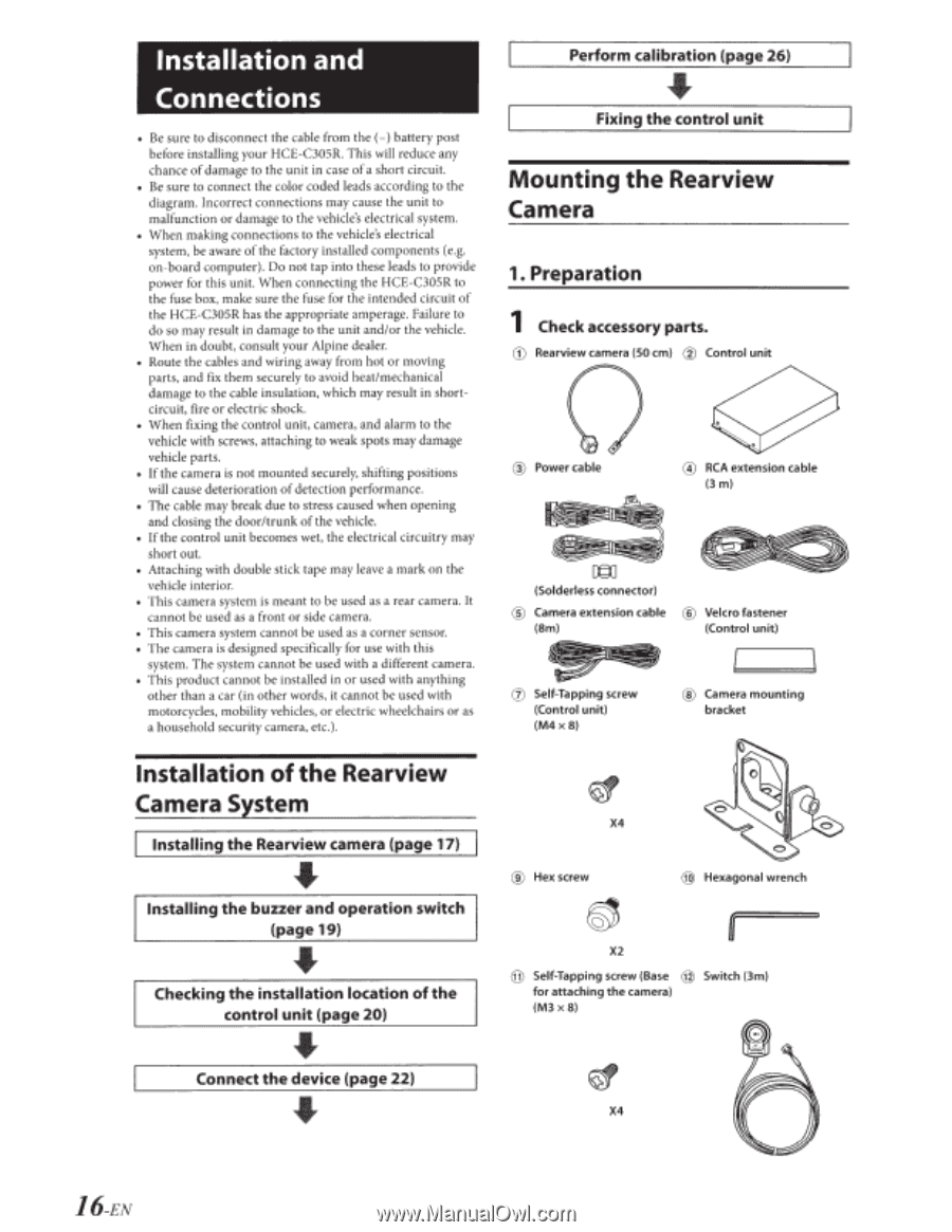
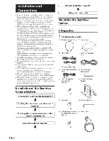
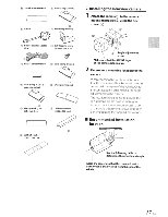
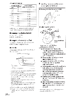
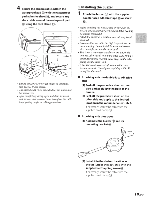
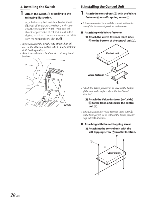
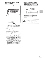
Installation and Connections Be sure to disconnect the cable from the (-) battery post before installing your HCE-C305R. This will reduce any chance of damage to the unit in case of a short circuit. • Be sure to connect the color coded leads according to the diagram. Incorrect connections may cause the unit to malfunction or damage to the vehicle's electrical system. • When making connections to the vehicle's electrical system, be aware of the factory installed components (e.g. on-board computer). Do not tap into these leads to provide power for this unit. When connecting the HCE-C305R to the fuse box, make sure the fuse for the intended circuit of the HCE-C305R has the appropriate amperage. Failure to do so may result in damage to the unit and/or the vehicle. When in doubt, consult your Alpine dealer. • Route the cables and wiring away from hot or moving parts, and fix them securely to avoid heat/mechanical damage to the cable insulation, which may result in shortcircuit, fire or electric shock. • When fixing the control unit, camera, and alarm to the vehicle with screws, attaching to weak spots may damage vehicle parts. • If the camera is not mounted securely, shifting positions will cause deterioration of detection performance. • The cable may break due to stress caused when opening and closing the door/trunk of the vehicle. • If the control unit becomes wet, the electrical circuitry may short out. • Attaching with double stick tape may leave a mark on the vehicle interior. • This camera system is meant to be used as a rear camera. It cannot be used as a front or side camera. • This camera system cannot be used as a corner sensor. • The camera is designed specifically for use with this system. The system cannot be used with a different camera. • This product cannot be installed in or used with anything other than a car (in other words, it cannot be used with motorcycles, mobility vehicles, or electric wheelchairs or as a household security camera, etc.). Perform calibration (page 26) Fixing the control unit Mounting the Rearview Camera 1. Preparation 1 Check accessory parts. ® CD Rearview camera (SO em) Control unit 0 ® Power cable @ RCA extension cable (3m) =[§] (Solderless connector) ® Camera extension cable (Bm) 00 ® Velcro fastener (Control unit) 0 Self-Tapping screw (Control unit) (M4x8) ® Camera mounting bracket Installation of the Rearview Camera System Installing the Rearview camera (page 17) Installing the buzzer and operation switch (page 19) Checking the installation location of the control unit (page 20) ~ X4 ® Hex screw @) Hexagonal wrench ~ ~ X2 @ Self-Tapping screw (Base @ Switch (3m) for attaching the camera) (M3x8) Connect the device (page 22) X4 16-EN
-
 1
1 -
2
-
3
-
4
-
5
-
6
-
7
-
8
-
9
-
10
-
11
-
 12
12 -
 13
13 -
 14
14 -
 15
15 -
 16
16 -
 17
17 -
 18
18 -
 19
19 -
 20
20 -
 21
21 -
 22
22 -
23
-
24
-
25
-
26
-
27
-
28
-
29
-
30
-
31
-
32
-
33
-
34
-
35
-
36
-
37
-
38
-
39
-
40
-
41
-
42
-
43
 |
 |