Alpine HCE-C305R Owners Manual - Page 18
Installing, Rearview camera, Recommended installation, location
 |
View all Alpine HCE-C305R manuals
Add to My Manuals
Save this manual to your list of manuals |
Page 18 highlights
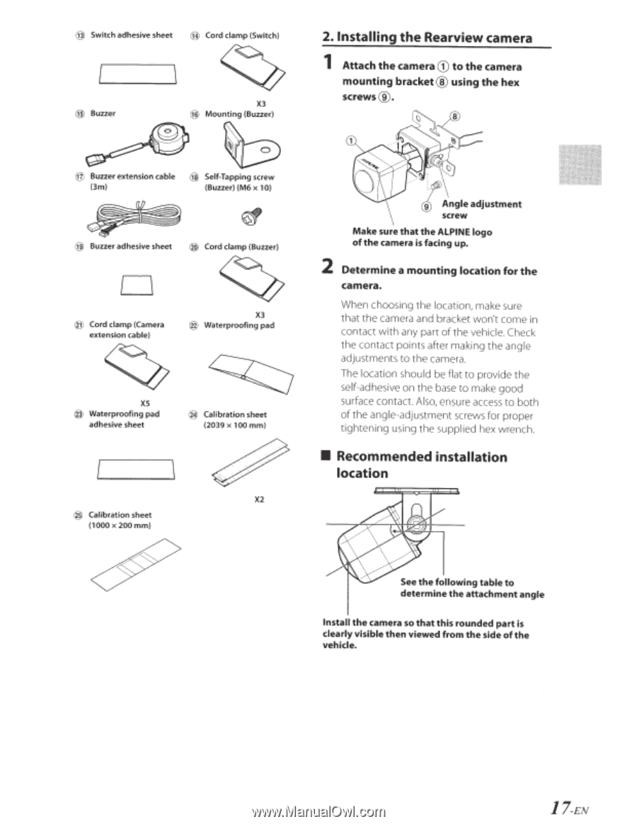
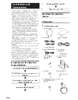
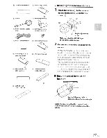
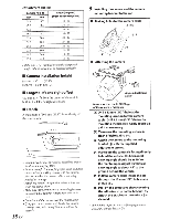
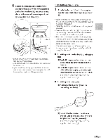
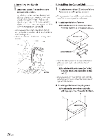
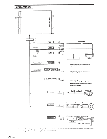
@ Switch adhesive sheet @ Cord clamp (Switch) @ Buzzer @ Buzzer extension cable (3m) X3 @ Mounting (Buzzer) ~ @ Self-Tapping screw (Buzzer) (M6 x 10) @) Buzzer adhesive sheet ® Cord clamp (Buzzer) D @ Cord clamp (Camera extension cable) X3 @ Waterproofing pad xs @ Waterproofing pad adhesive sheet @ Calibration sheet (2039 x 100 mm) X2 ® Calibration sheet (1000 x 200 mm) 2. Installing the Rearview camera 1 Attach the camera CD to the camera mounting bracket® using the hex screws@. 8 tAngle adjustment screw Make sure that the ALPINE logo of the camera is facing up. 2 Determine a mounting location for the camera. When choosing the location, make sure that the camera and bracket won't come in contact with any part of the vehicle. Check the contact points after making the angle adjustments to the camera. The location should be flat to provide the self-adhesive on the base to make good surface contact. Also, ensure access to both of the angle-adjustment screws for proper tightening using the supplied hex wrench. • Recommended installation location See the following table to determine the attachment angle Install the camera so that this rounded part is clearly visible then viewed from the side of the vehicle. 17-EN
-
 1
1 -
2
-
3
-
4
-
5
-
6
-
7
-
8
-
9
-
10
-
11
-
12
-
 13
13 -
 14
14 -
 15
15 -
 16
16 -
 17
17 -
 18
18 -
 19
19 -
 20
20 -
 21
21 -
 22
22 -
 23
23 -
24
-
25
-
26
-
27
-
28
-
29
-
30
-
31
-
32
-
33
-
34
-
35
-
36
-
37
-
38
-
39
-
40
-
41
-
42
-
43
 |
 |