Asus T2-AH1 T2-AH1 English user manual E2065
Asus T2-AH1 Manual
 |
View all Asus T2-AH1 manuals
Add to My Manuals
Save this manual to your list of manuals |
Asus T2-AH1 manual content summary:
- Asus T2-AH1 | T2-AH1 English user manual E2065 - Page 1
Terminator 2 Barebone System Model T2-AH1 MODE - Asus T2-AH1 | T2-AH1 English user manual E2065 - Page 2
Product warranty or service will not be extended if: (1) the product is repaired, modified or altered, unless such repair, modification of alteration is authorized in writing by ASUS; or (2) the serial number of the product is defaced or missing. ASUS PROVIDES THIS MANUAL "AS IS" WITHOUT WARRANTY - Asus T2-AH1 | T2-AH1 English user manual E2065 - Page 3
Table of contents Notices vi Safety information vii About this guide viii System package contents x Chapter 1: System Introduction 1.1 Welcome 1-2 1.2 Installing a CPU 2-5 2.5.1 CPU installation 2-5 2.5.2 Installing the CPU fan and heatsink assembly ........ 2-7 2.5.3 Removing the CPU fan and - Asus T2-AH1 | T2-AH1 English user manual E2065 - Page 4
Virtual Cable Tester 3-14 3.4.5 Cool 'n' Quiet!™ Technology 3-15 3.4.6 ASUS PC Probe II 3-17 3.4.7 AC`97 audio feature 3-23 Chapter 4: Motherboard Info 4.1 Introduction 4-2 4.2 Motherboard layout 4-2 4.3 Jumper 4-3 4.4 Connectors 4-4 Chapter 5: BIOS Information 5.1 Managing and updating your - Asus T2-AH1 | T2-AH1 English user manual E2065 - Page 5
Pop-up window 5-13 CPU Configuration 5-23 5.4.6 Chipset 5-24 5.4.7 Onboard Devices Configuration 5-26 5.4.8 PCI Express Configuration 5-27 5.4.9 PCI PnP 5-28 5.5 Power menu 5-29 5.5.1 Suspend Mode 5-29 5.5.2 Repost Video on S3 Resume 5-29 5.5.3 ACPI 2.0 Support 5-29 5.5.4 ACPI APIC Support - Asus T2-AH1 | T2-AH1 English user manual E2065 - Page 6
and, if not installed and used in accordance with manufacturer's instructions, may cause harmful interference to radio communications. However, there is reception, which can be determined by turning the equipment off and on, the user is encouraged to try to correct the interference by one or more of - Asus T2-AH1 | T2-AH1 English user manual E2065 - Page 7
in any area where it may become wet. Place the product on a stable surface. • If you encounter technical problems with the product, contact a qualified service technician or your retailer. Lithium-Ion Battery Warning C A U T I O N: Danger of explosion if battery is incorrectly replaced. Replace only - Asus T2-AH1 | T2-AH1 English user manual E2065 - Page 8
About this guide Audience This guide provides general information and installation instructions about the ASUS T2-AH1 barebone system. This guide is intended for experienced users and integrators with hardware knowledge of personal computers. How this guide is organized This guide contains the - Asus T2-AH1 | T2-AH1 English user manual E2065 - Page 9
Conventions used in this guide W A R N I N G : Information to prevent injury to yourself when trying to complete a task. C A U T I O N : Information to prevent damage to the components when trying to complete a task. I M P O R T A N T : Instructions that you MUST follow to complete a task. N O T E : - Asus T2-AH1 | T2-AH1 English user manual E2065 - Page 10
contents Check your T2-AH1 system package for the following items. If any of the items is damaged or missing, contact your retailer immediately. Item description 1 . A S U S T 2 - A H 1 b a r e b o n e s y s t e m with • ASUS motherboard • 250 W PFC power supply unit • Gigabit LAN port • CPU fan and - Asus T2-AH1 | T2-AH1 English user manual E2065 - Page 11
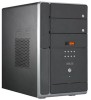
System introduction Chapter 1 This chapter gives a general description of the ASUS T2-AH1. The chapter lists the system features including introduction on the front and rear panel, and internal components. MODE ASUS T2-AH1 - Asus T2-AH1 | T2-AH1 English user manual E2065 - Page 12
T2-AH1 is an all-in-one barebone system with a versatile home entertainment feature. The system comes in a stylish mini-tower casing, and powered by the ASUS motherboard that supports the AMD Athlon™ 64 processor for Socket 939 with 1 GHz/800 MHz/400 MHz FSB and up to 2 GB system memory. With audio - Asus T2-AH1 | T2-AH1 English user manual E2065 - Page 13
put the Audio DJ function to CD mode. In Windows® mode, pressing audio CD track. In R a d i o m o d e, scans the available FM stations when pressed for less than two seconds or presets a station when pressed for more than two seconds. Refer to page 3-13 on how to preset a radio station. ASUS T2-AH1 - Asus T2-AH1 | T2-AH1 English user manual E2065 - Page 14
played. 1 5 . P R E V I O U S b u t t o n . Press this button to perform various functions in different modes. In C D m o d e, selects the previous audio track. In R a d i o m o d e, selects the previous preset station. 1 6 . N E X T b u t t o n . Press this button to perform various functions in - Asus T2-AH1 | T2-AH1 English user manual E2065 - Page 15
door if a storage card is inserted into any of the card slots. • Use and format a storage card according to the documentation that comes with it. ASUS T2-AH1 1-5 - Asus T2-AH1 | T2-AH1 English user manual E2065 - Page 16
, camera, PDA, and others. 2 8 . 4 - p i n I E E E 1 3 9 4 a p o r t . This port provides high-speed connectivity for IEEE 1394a-compliant audio/video devices, storage peripherals, and other PC devices. 2 9 . 6 - p i n I E E E 1 3 9 4 a p o r t . This port provides high-speed connectivity for IEEE - Asus T2-AH1 | T2-AH1 English user manual E2065 - Page 17
or a speaker. In 4/6-channel mode, the function of this port becomes Front Speaker Out. 9 . L i n e I n p o r t . This Line In (light blue) port connects a tape player or other audio sources. In 4/6-channel mode, the function of this port becomes Surround output. ASUS T2-AH1 1-7 - Asus T2-AH1 | T2-AH1 English user manual E2065 - Page 18
u t p o r t s (red and white). These ports connect the left and right audio input cable jacks to the television or VCR left audio output port. 1 5 . V i d e o O u t p o r t (yellow). This port connects a video cassette recorder (VCR). 1 6 . C h a s s i s f a n v e n t . This vent is for the fan that - Asus T2-AH1 | T2-AH1 English user manual E2065 - Page 19
labeled for your reference. Proceed to Chapter 2 for instructions on installing additional system components. 8 9 13 12 ASUS motherboard 10. CPU socket 11. DIMM sockets 12. Expansion slots 13. PCI Express™ x16 slot for discrete graphics card 14. PCI slot 15. Serial ATA connectors ASUS T2-AH1 - Asus T2-AH1 | T2-AH1 English user manual E2065 - Page 20
stand-by mode, Suspend-to-RAM, Suspend-to-Disk, or Wait Boot state. Enter the BIOS setup or the operating system to adjust the time. Audio DJ mode The LED panel displays various information when the system is in Audio DJ mode. In C D m o d e, the LED panel displays the play/pause icon, number, and - Asus T2-AH1 | T2-AH1 English user manual E2065 - Page 21
Basic installation Chapter 2 This chapter provides step-by-step instructions on how to install components in the system. MODE ASUS T2-AH1 - Asus T2-AH1 | T2-AH1 English user manual E2065 - Page 22
Basic components to install 1. Central processing unit (CPU) 2. DDR Dual Inline Memory Module (DIMM) Floppy disk drive Tool Phillips (cross) screw driver 2.2 Before you proceed Take note of the the bag that came with the component. The motherboard comes with an onboard standby power LED. This LED - Asus T2-AH1 | T2-AH1 English user manual E2065 - Page 23
cover to the chassis. RADIO ANY 1 1 2. Use a Phillips screw driver to remove the cover screws. Keep the screws for later use. 2 3. Slightly pull the cover toward the rear panel until the side tabs are disengaged from the chassis. 4. Lift the cover, then set aside. 2 2 4 3 3 ASUS T2-AH1 2-3 - Asus T2-AH1 | T2-AH1 English user manual E2065 - Page 24
supply unit (PSU) before you can install a central processing unit( CPU) and other system components. To remove the PSU: 1. Lay the 7. Disconnect the power plugs on the motherboard, then set the PSU aside. When removing the PSU, make sure to hold or support it firmly. The unit may accidentally - Asus T2-AH1 | T2-AH1 English user manual E2065 - Page 25
data paths. Take note of the marked corner (with gold triangle) on the CPU. This mark should match a specific corner on the socket to ensure correct installation. Gold triangle 2.5.1 CPU installation To install a CPU: 1. Locate the CPU socket on the motherboard. CPU Socket 939 ® ASUS T2-AH1 2-5 - Asus T2-AH1 | T2-AH1 English user manual E2065 - Page 26
lift it up to a 90°-100° angle. Make sure that the socket lever is lifted up to 90°-100° angle, otherwise the CPU does not fit in completely. 3. Position the CPU above the socket such that the CPU corner with the gold triangle matches the socket corner with a small triangle. 4. Carefully insert the - Asus T2-AH1 | T2-AH1 English user manual E2065 - Page 27
hole of the retention module. 6. Carefully press down each locking lever. 7. Hook its end into the retention module hole. Do not forget to connect the CPU fan connector! Hardware monitoring errors may occur if you fail to plug this connector. 6 4 2 5 6 7 7 5 4 3 ASUS T2-AH1 2-7 - Asus T2-AH1 | T2-AH1 English user manual E2065 - Page 28
your computer and unplug the cable from the power source before removing the CPU fan and heatsink assembly. To remove the CPU fan and heatsink assembly: 1. Disconnect the CPU fan cable from the CPU fan connector on the motherboard. 2. Carefully press down the locking lever. 3. Unhook the end of the - Asus T2-AH1 | T2-AH1 English user manual E2065 - Page 29
2.6 Installing a DIMM The system motherboard comes with two Double Data Rate (DDR) Dual Inline Memory Module ( total system memory size when you enable the onboard VGA. • This motherboard does not support memory modules made up of 128 Mb chips or double-sided x16 memory modules. ASUS T2-AH1 2-9 - Asus T2-AH1 | T2-AH1 English user manual E2065 - Page 30
(blue) DIMM_B1 (black) (1) Installed (2)* Installed - Installed * Use only identical DDR DIMM pairs. DDR (400 MHz) Qualified Vendors List DIMM support Size Vendor Model Brand Side/s* Component CL A B 256 MB KINGSTON KVR400X72C3A/256 Mosel SS V58C2256804SAT5(ECC) - • • 512 MB KINGSTON - Asus T2-AH1 | T2-AH1 English user manual E2065 - Page 31
DIMM support Size Vendor Model Brand Side/s* Component C L A B 256 MB TwinMOS M2G9I08AIATT9F081AADT TwinMOS SS TMD7608F8E50D 2.5 • • 512 CENTURY 256 MB CENTURY DXV2S8EL5B/HP DXV6S8MC5B - DS DD2508AKTA-5B-E - • • - SS MT46V32M8TG-5BG - • • (Continued on the next page) ASUS T2-AH1 2-11 - Asus T2-AH1 | T2-AH1 English user manual E2065 - Page 32
into either slot, in a Single-channel memory configuration. B - supports one pair of modules inserted into both slots as one pair of Dual-channel memory configuration. S S - Single-sided D S - Double-sided Obtain DDR DIMMs only from ASUS qualified vendors. Refer to the Qualified DDR400 vendors list - Asus T2-AH1 | T2-AH1 English user manual E2065 - Page 33
2.6.2 DIMM installation To install a DDR DIMM: 1. Locate the two DIMM sockets on the motherboard. Retaining clips 2. Unlock a socket by pressing the retaining clips outward. 3. Align a DIMM on in only one direction. DO NOT force a DIMM into a socket to avoid damaging the DIMM! ASUS T2-AH1 2-13 - Asus T2-AH1 | T2-AH1 English user manual E2065 - Page 34
cards that comply with PCI specifications. The following figure shows a LAN card installed on a PCI slot. PCI Express™ x16 slot This motherboard supports PCI Express™ x16 graphic cards that comply with PCI Express™ specifications. The figure shows a graphics card installed on the PCI Express™ x16 - Asus T2-AH1 | T2-AH1 English user manual E2065 - Page 35
press firmly until the card is completely seated on the slot. 4 PCI card 5. Replace the expansion card lock to secure the card to the chassis. 5 ASUS T2-AH1 2-15 - Asus T2-AH1 | T2-AH1 English user manual E2065 - Page 36
are usually available for ISA or PCI devices. IRQ assignments for this motherboard USB0 USB1 USB2 USB3 AC '97 Onboard 1394 Onboard LAN Onboard PCIE used When using a PCI card on shared slots, ensure that the drivers support "Share IRQ" or that the cards do not need IRQ assignments; otherwise - Asus T2-AH1 | T2-AH1 English user manual E2065 - Page 37
2.8 Installing an optical drive The barebone system comes with two 5.25-inch drive bays for two optical drives. • You may install a second optical hooks. 3 3 1 2 3 3 4 4 5. Slightly push the front panel cover outward until it detaches from the chassis, then set it aside. 5 ASUS T2-AH1 2-17 - Asus T2-AH1 | T2-AH1 English user manual E2065 - Page 38
other end of the IDE ribbon cable is connected to the IDE connector (blue connector labeled IDE) on the motherboard. See page 4-7 for the location of the IDE connector. 12. Connect the other end of the audio cable to the 4-pin CDconnector on the motherboard. See page 4-7 for the location of the CD - Asus T2-AH1 | T2-AH1 English user manual E2065 - Page 39
13. Reinstall the front panel cover by aligning its hooks with the chassis holes. 14. Lock the front panel cover hooks to the chassis holes as indicated. 13 14 ASUS T2-AH1 2-19 - Asus T2-AH1 | T2-AH1 English user manual E2065 - Page 40
barebone system comes with one 3.25-inch drive bay for a floppy disk drive. To install a floppy disk drive: 1. Remove the front panel cover. For instructions cable to the floppy disk drive connector (labeled FLOPPY) on the motherboard. See page 4-6 for the connector location. 6. Connect a power - Asus T2-AH1 | T2-AH1 English user manual E2065 - Page 41
supports one Ultra ATA/133 IDE or one Serial ATA hard disk drive. To install an IDE hard disk drive: 1. Locate the HDD tray lock screw on the other side of the chassis. 2. Remove the lock screw with a Philips screw driver documentation on how to set the drive as a Master device. ASUS T2-AH1 2-21 - Asus T2-AH1 | T2-AH1 English user manual E2065 - Page 42
the power supply unit plugs. 9 10. Connect the other end of the IDE ribbon cable to the IDE connector (blue connector labeled IDE) on the motherboard. See page 4-7 for the location of the IDE connector. 2-22 Chapter 2: Basic installation - Asus T2-AH1 | T2-AH1 English user manual E2065 - Page 43
15-pin SATA power plug If your Serial ATA HDD has both 4-pin and 15-pin connectors at the back, use either the 15-pin SATA power adapter plug O R the legacy 4-pin power connector. D O N O T use both to prevent damage to components and to keep the system from becoming unstable. ASUS T2-AH1 2-23 - Asus T2-AH1 | T2-AH1 English user manual E2065 - Page 44
4-pin 12 V power plug to the ATX12V connector on the motherboard. 2. Connect the 24-pin ATX power plug to the ATXPWR connector on the motherboard. See page 4-6 for the location of power connectors. 2 PSU cables do not interfere with the CPU and/or chassis fans. 6 2-24 Chapter 2: Basic installation - Asus T2-AH1 | T2-AH1 English user manual E2065 - Page 45
supply in your area is 200-240 V, set the switch to 230 V. Setting the switch to 115 V in a 230 V environment will seriously damage the system! ASUS T2-AH1 2-25 - Asus T2-AH1 | T2-AH1 English user manual E2065 - Page 46
2.12 Replacing the cover To replace the cover: 1. Turn the chassis upright. 3 2. Position the front edge of the cover at least two inches from the front panel cover. Fit the cover tabs with the chassis rail and the front panel tabs. 3. Lower the rear edge of the cover as shown. 4. Push the cover - Asus T2-AH1 | T2-AH1 English user manual E2065 - Page 47
Chapter 3 This chapter helps you power up the system and install drivers and utilities from the support CD. MODE ASUS T2-AH1 Starting up - Asus T2-AH1 | T2-AH1 English user manual E2065 - Page 48
3.1 Installing an operating system The barebone system supports Windows® 2000/XP operating systems (OS). Always install the latest OS version and corresponding updates so you can maximize the features of your hardware. Because motherboard settings and hardware options vary, use the setup procedures - Asus T2-AH1 | T2-AH1 English user manual E2065 - Page 49
ASUS InstAll Installation Wizard for Drivers Launches the ASUS InstallAll driver installation wizard. AMD Cool 'n' Quiet Driver Launches the AMD Cool 'n' Quiet™ Technology driver installation wizard. ATI Radeon Xpress 200 Chipset Driver Installs the ATI Radeon Xpress 200 Chipset driver. ASUS T2-AH1 - Asus T2-AH1 | T2-AH1 English user manual E2065 - Page 50
. Marvell Yukon Gigabit Ethernet Driver Installs the Marvell® Gigabit Ethernet LAN Driver. USB 2.0 Driver Installs the USB 2.0 driver. 3.3.3 Utilities menu The Utilities menu shows the applications and other software that the motherboard supports. ASUS InstAll Installation Wizard for Utilities - Asus T2-AH1 | T2-AH1 English user manual E2065 - Page 51
on any detected problems. This utility helps you keep your computer in a healthy operating condition. ASUS Update Installs the ASUS Update that allows you to update the motherboard BIOS and drivers. This utility requires an Internet connection either through a network or an Internet Service Provider - Asus T2-AH1 | T2-AH1 English user manual E2065 - Page 52
3.3.4 Make Disk menu The M a k e D i s k menu allows you to create driver disks. Make ULi 32/64bit SATA Driver Disk Allows you to create a ULi Serial ATA driver disk for a 32/64-bit system. 3-6 Chapter 3: Starting up - Asus T2-AH1 | T2-AH1 English user manual E2065 - Page 53
3.3.5 ASUS contact information The Contact tab displays the ASUS contact information. 3.3.6 Other information The icons on the top right side of the screen provide additional information on the motherboard and the contents of the support CD. ASUS T2-AH1 3-7 - Asus T2-AH1 | T2-AH1 English user manual E2065 - Page 54
using the optional radio module. By default, the radio region of the ASUS FM radio module is set to E u r o p e. If you purchased the barebone system outside Europe (U S A or J a p a n), you must change the radio region in the BIOS setup to receive FM radio signals. See section "5.4.1 Instant Music - Asus T2-AH1 | T2-AH1 English user manual E2065 - Page 55
radio station: 1. Click the E d i t button. An E d i t C h a n n e l window appears. 2. Select a radio station you want to edit, then click the E d i t button. 3. Another E d i t C h a n n e l window appears. 4. Edit the station frequency and name. Click O K when you are done. ASUS T2-AH1 3-9 - Asus T2-AH1 | T2-AH1 English user manual E2065 - Page 56
3.4.2 ASUS Instant Music The motherboard is equipped with a BIOS-based audio playback feature called I n s t a n t M u s i c. The onboard audio AC'97 CODEC supports this feature, which requires an optical drive (CD-ROM, DVD-ROM, or CD-RW). • Instant Music only supports CDs in audio format. • Instant - Asus T2-AH1 | T2-AH1 English user manual E2065 - Page 57
F7 F8 To guide you in using Instant Music, place the Instant Music label over the function keys on the keyboard. The Instant Music keyboard label comes with your motherboard package. Instant once to stop playing the audio CD. Press or again to eject the CD. ASUS T2-AH1 3-11 - Asus T2-AH1 | T2-AH1 English user manual E2065 - Page 58
power plug to an electrical outlet. 2. Press the CD button ( ) on the front panel to put the system in Audio DJ mode. Playing an audio CD/DVD To play an audio CD/DVD: 1. Insert an audio CD/DVD to the optical drive. 2. Press the PLAY/PAUSE ( / ) button to start playing the first track of - Asus T2-AH1 | T2-AH1 English user manual E2065 - Page 59
Presetting a station To preset a radio station: 1. Put the Audio DJ in radio mode. 2. Select the radio station you wish to preset by pressing the PLAY/PAUSE ( / ) button the volume. Connect a headphone or PC speakers to the rear or front panel Line Out port for audio output. ASUS T2-AH1 3-13 - Asus T2-AH1 | T2-AH1 English user manual E2065 - Page 60
problems, and pair skew problems of up to 64 ns at one meter accuracy. The VCT feature reduces networking and support The VCT only runs on systems with Windows® XP or Windows® 2000 operating systems. • The VCT the Virtual Cable Tester™ main window is disabled if no problem is detected on the LAN - Asus T2-AH1 | T2-AH1 English user manual E2065 - Page 61
e r . . . button. The following dialog box appears. 5. From the P o w e r s c h e m e s combo list box, select M i n i m a l P o w e r M a n a g e m e n t. 6. Click O K to effect settings. Make sure to install the Cool 'n' Quiet!™ driver and application before using this feature. ASUS T2-AH1 3-15 - Asus T2-AH1 | T2-AH1 English user manual E2065 - Page 62
to install the Cool 'n' Quiet!™ software from the motherboard support CD. Refer to section "3.3.3 Utilities menu" for details. To launch the Cool 'n' Quiet!™ program: 1. If you are using Windows® 2000, click the S t a r t button. Select Programs-> ASUS -> Cool & Quiet -> Cool & Quiet. 2. If you are - Asus T2-AH1 | T2-AH1 English user manual E2065 - Page 63
of your system and change the utility configuration. By default, the main window displays the P r e f e r e n c e section. You can close or restore the P r e f e r e n c e section by clicking on the triangle on the main window right handle. Click to close the Preference panel ASUS T2-AH1 3-17 - Asus T2-AH1 | T2-AH1 English user manual E2065 - Page 64
Opens the hard disk drive, memory, CPU usage window Shows/Hides the P r e f e r e n c e section Minimizes the application Closes the application Sensor alert When a system sensor detects a problem, the main window right handle turns red, as the illustrations below show. When displayed, the monitor - Asus T2-AH1 | T2-AH1 English user manual E2065 - Page 65
display the current value of a system sensor such as fan rotation, CPU temperature, and voltages. The hardware monitor panels come in two display modes window. You cannot adjust the sensor threshold values in a small monitoring panel. Click to increase value Click to decrease value ASUS T2-AH1 - Asus T2-AH1 | T2-AH1 English user manual E2065 - Page 66
value. Refer to the illustrations below. Small display Large display WMI browser Click to display the WMI (Windows Management Instrumentation) browser. This browser displays various Windows® management information. Click an item from the left panel to display on the right panel. Click the - Asus T2-AH1 | T2-AH1 English user manual E2065 - Page 67
the CPU, hard disk drive space, and memory usage. Click to display the Usage browser. CPU usage The C P U tab displays real-time CPU usage in line graph representation. If the CPU has pie chart at the bottom of the window represents the used (blue) and the available HDD space. ASUS T2-AH1 3-21 - Asus T2-AH1 | T2-AH1 English user manual E2065 - Page 68
the available physical memory. Configuring PC Probe II Click to view and adjust the sensor threshold values. The C o n f i g window has two tabs: S e n s o r / T h r e s h o l d and P r e f e r e n c e. changes *Available on some motherboards only. Loads your saved configuration Saves your configuration - Asus T2-AH1 | T2-AH1 English user manual E2065 - Page 69
drivers and application: 1. Place the support CD in the optical drive. 2. When the drivers menu appears, click R e a l t e k A u d i o Driver. 3. Installation begins automatically. Click N e x t . 4. The S e t u p S t a t u s window appears, indicating the progress of the installation. ASUS T2-AH1 - Asus T2-AH1 | T2-AH1 English user manual E2065 - Page 70
5. The drivers are installed into your system. 6. The I n s t a l l S h i e l d W i z a r d C o m p l e t e window appears, indicating that installation is is automatically created on your desktop after you installed the audio drivers and application. To launch the application, simply double-click - Asus T2-AH1 | T2-AH1 English user manual E2065 - Page 71
options Create file Save recorded data to file Add file to playlist Remove file from playlist Clear playlist Save playlist to file Load playlist file ASUS T2-AH1 3-25 - Asus T2-AH1 | T2-AH1 English user manual E2065 - Page 72
3-26 Chapter 3: Starting up - Asus T2-AH1 | T2-AH1 English user manual E2065 - Page 73
Motherboard info Chapter 4 This chapter gives information about the motherboard that comes with the system. This chapter includes the motherboard layout, jumper settings, and connector locations. MODE ASUS T2-AH1 - Asus T2-AH1 | T2-AH1 English user manual E2065 - Page 74
ASUS motherboard comes already installed in the ASUS T2-AH1 system. This chapter provides technical information about the motherboard for future upgrades or system reconfiguration. 4.2 Motherboard 184-pin module) EATXPWR Super I/O Flash BIOS BUZZER SATA2 SATA4 SATA1 VIA VT6307 Marvell 88E8053 - Asus T2-AH1 | T2-AH1 English user manual E2065 - Page 75
the key during the boot process and enter BIOS setup to re-enter data. ® Clear RTC RAM CLRTC 12 23 Normal (Default) Clear CMOS Except when clearing the RTC RAM, never remove the cap on CLRTC jumper default position. Removing the cap will cause system boot failure. ASUS T2-AH1 4-3 - Asus T2-AH1 | T2-AH1 English user manual E2065 - Page 76
front panel I/O daughterboard to support the front panel audio I/O ports. ® Front panel audio connector FP_AUDIO MIC2 MICPWR Line out_R NC Line out_L AGND +5VA BLINE_OUT_R BLINE_OUT_L 2 . Digital audio connector (8-2 pin SPDIF) (A) is for the SPDIF connector on the motherboard while (B) is for - Asus T2-AH1 | T2-AH1 English user manual E2065 - Page 77
to connect the fan cables to the fan connectors. Insufficient air flow within the system may damage the motherboard components. These are not jumpers! DO NOT place jumper caps on the fan connectors! CPU_FAN GND CPUFANPWR SYSFANIN ® Fan connectors ASUS T2-AH1 CHA_FAN GND CPUFANPWR CPUFANIN 4-5 - Asus T2-AH1 | T2-AH1 English user manual E2065 - Page 78
# Ground Ground +3 Volts -12 Volts +3 Volts +3 Volts Do not forget to connect the 4-pin ATX12V power plug to the ATX12V connector on the motherboard; otherwise, the system will not boot up. 6 . Floppy disk drive connector (34-1 pin FLOPPY) This connector is for the provided floppy disk drive - Asus T2-AH1 | T2-AH1 English user manual E2065 - Page 79
primary IDE connector on the motherboard, a black connector for an audio input from sound sources such as a CD-ROM, TV tuner, or MPEG card. AUX CD (White) (Black) ® Right Audio Channel Ground Left Audio Channel Right Audio Channel Ground Left Audio Channel Internal audio connectors ASUS T2-AH1 - Asus T2-AH1 | T2-AH1 English user manual E2065 - Page 80
connectors are for the Serial ATA signal cables for Serial ATA hard disk drives. ® SATA connectors SATA4 SATA2 GND TXP4 TXN4 GND RXP4 RXN4 GND GND TXP2 TXN2 GND RXP2 RXN2 install Windows® 2000 or the Windows® XP/2003 before using Serial ATA hard disk drives. 4-8 Chapter 4: Motherboard info - Asus T2-AH1 | T2-AH1 English user manual E2065 - Page 81
daughterboard. USB5 is for the remote controller. USB6 and USB7 are for the user's USB devices to be connected on the front I/O. • System power LED (1- BIOS settings. • DJ button (1-pin DJ BTN) This is for the Audio DJ module on the front panel to support the Audio DJ buttons. ASUS T2-AH1 4-9 - Asus T2-AH1 | T2-AH1 English user manual E2065 - Page 82
4-10 Chapter 4: Motherboard info - Asus T2-AH1 | T2-AH1 English user manual E2065 - Page 83
Chapter 5 This chapter tells how to change system settings through the BIOS Setup menus and describes the BIOS parameters. BIOS setup MODE ASUS T2-AH1 1 - Asus T2-AH1 | T2-AH1 English user manual E2065 - Page 84
a floppy disk during POST.) 3. A S U S C r a s h F r e e B I O S 2 (Updates the BIOS using a bootable floppy disk or the motherboard support CD when the BIOS file fails or gets corrupted.) 4. A S U S U p d a t e (Updates the BIOS in Windows® environment.) Refer to the corresponding sections for - Asus T2-AH1 | T2-AH1 English user manual E2065 - Page 85
appears if there is no floppy disk in the drive. A "A8R4T.ROM not found!" error message appears if the correct BIOS file is not found in the floppy disk. Make sure that you rename the BIOS file to A8R4T.ROM. • The EZ Flash utility does not support BIOS update using a USB floppy. ASUS T2-AH1 5-3 - Asus T2-AH1 | T2-AH1 English user manual E2065 - Page 86
actual BIOS screen displays may not be exactly the same as shown. 1. Copy the AFUDOS utility (afudos.exe) from the motherboard support CD to the bootable floppy disk you created earlier. 2. Boot the system in DOS mode, then at the prompt type: afudos /o[filename] where the [filename] is any user - Asus T2-AH1 | T2-AH1 English user manual E2065 - Page 87
(www.asus.com) and download the latest BIOS file for the motherboard. Save the BIOS file to a bootable floppy disk. Write the BIOS filename on a piece of paper. You need to type the exact BIOS filename at the DOS prompt. 2. Copy the AFUDOS utility (afudos.exe) from the motherboard support CD to - Asus T2-AH1 | T2-AH1 English user manual E2065 - Page 88
restart your computer A:\> 5.1.4 ASUS CrashFree BIOS 2 utility The ASUS CrashFree BIOS 2 is an auto recovery tool that allows you to restore the BIOS file when it fails or gets corrupted during the updating process. You can update a corrupted BIOS file using the motherboard support CD or the floppy - Asus T2-AH1 | T2-AH1 English user manual E2065 - Page 89
optical drive for the original or updated BIOS file. The utility then updates the corrupted BIOS file. Bad BIOS checksum. Starting BIOS recovery... Checking for floppy... Floppy not found! Checking for CD-ROM... CD-ROM found! Reading file "A8R4T.ROM". Completed. Start flashing... ASUS T2-AH1 5-7 - Asus T2-AH1 | T2-AH1 English user manual E2065 - Page 90
not be the latest BIOS version for this motherboard. Visit the ASUS website (www.asus.com) to download the latest BIOS file. 5.1.5 ASUS Update utility The ASUS Update is a utility that allows you to manage, save, and update the motherboard BIOS in Windows® environment. The ASUS Update utility allows - Asus T2-AH1 | T2-AH1 English user manual E2065 - Page 91
S U p d a t e. The ASUS Update main window appears. 2. Select U p d a t e B I O S f r o m 3. Select the ASUS FTP site t h e I n t e r n e t option from the nearest you to avoid network drop-down menu, then click traffic, or click A u t o S e l e c t. N e x t. Click N e x t. ASUS T2-AH1 5-9 - Asus T2-AH1 | T2-AH1 English user manual E2065 - Page 92
to download. Click Next. 5. Follow the screen instructions to complete the update process. The ASUS Update utility is capable of updating itself through the Internet. Always update the utility to avail all its features. Updating the BIOS through a BIOS file To update the BIOS through a BIOS file - Asus T2-AH1 | T2-AH1 English user manual E2065 - Page 93
under the Exit Menu. See section "5.7 Exit Menu." • The BIOS setup screens shown in this section are for reference purposes only, and may not exactly match what you see on your screen. • Visit the ASUS website (www.asus.com) to download the latest BIOS file for this motherboard. ASUS T2-AH1 5-11 - Asus T2-AH1 | T2-AH1 English user manual E2065 - Page 94
5.2.1 BIOS menu screen Menu items Menu bar Configuration fields General help System Time System Date Legacy Diskette A IDE Master IDE Slave System Information [16:37:21] [Fri,05/13/2005] [1.44M, 3.5 in.] [ST320410A] [ASUS CD-S520/A] Use [ENTER], [TAB] or [SHIFT-TAB] to select a field. Use [+] or - Asus T2-AH1 | T2-AH1 English user manual E2065 - Page 95
field opposite the item. You cannot select an item that is not user-configurable. A configurable field is enclosed in brackets, and is highlighted 5.2.9 General help Pop-up window At the top right corner of the menu screen is a brief description of the selected item. Scroll bar ASUS T2-AH1 5-13 - Asus T2-AH1 | T2-AH1 English user manual E2065 - Page 96
an overview of the basic system information. Refer to section "5.2.1 BIOS menu screen" for information on the menu screen items and how System Information [16:37:21] [Fri,05/13/2005] [1.44M, 3.5 in.] : [ST320410A] : [ASUS CD-S520/A] Use [ENTER], [TAB] or [SHIFT-TAB] to select a field. Use [+] or - Asus T2-AH1 | T2-AH1 English user manual E2065 - Page 97
When set to Auto, the data transfer from and to the device occurs multiple sectors at a time if the device supports multi-sector transfer feature. When set to [Disabled], the data transfer from and to the device occurs one sector at a time. Configuration options: [Disabled] [Auto] ASUS T2-AH1 5-15 - Asus T2-AH1 | T2-AH1 English user manual E2065 - Page 98
/15/05 Processor Type Speed Count : AMD Athlon (tm) 64 Processor 3200+ : 2000 MHz : 1 System Memory Size : 192 MB AMI BIOS Displays the auto-detected BIOS information. Processor Displays the auto-detected CPU specification. System Memory Displays the auto-detected system memory. 5-16 Chapter - Asus T2-AH1 | T2-AH1 English user manual E2065 - Page 99
Instant Music Configuration JumperFree Configuration LAN Cable Status USB Configuration CPU Configuration Chipset Onboard Devices Configuration PCI Express Configuration PCI PnP Configure ] Set the Instant Music item to [Enabled] if you want to enable the ASUS Audio DJ function. ASUS T2-AH1 5-17 - Asus T2-AH1 | T2-AH1 English user manual E2065 - Page 100
Allows you to select the overclocking options to achieve the desired CPU internal frequency. Select either one of the preset overclocking configiuration r c l o c k P r o f i l e - loads overclocking profiles with optimal parameters for stability when overclocking. 5-18 Chapter 5: BIOS setup - Asus T2-AH1 | T2-AH1 English user manual E2065 - Page 101
to [Manual]. CPU Frequency [XXX] Displays the frequency sent by the clock generator to the system bus and PCI bus. The value of this item is auto-detected by the BIOS. Use the < + > and < - > keys to adjust the CPU frequency. Configuration options: [2.60V] [2.70V] [2.80V] [2.90V] ASUS T2-AH1 5-19 - Asus T2-AH1 | T2-AH1 English user manual E2065 - Page 102
BIOS to user config mode. Configuration options: [Auto] [Manual] Burst Length [4 Beats] Allows you to set the burst length. Configuration options: [8 Beats] [4 Beats] [2 Beats] Hardware Memory Hole [Disabled] Allows you to enable or disable remapping around the memory hole. This feature is supported - Asus T2-AH1 | T2-AH1 English user manual E2065 - Page 103
enabled, the menu reports the cable faults or shorts, and displays the point (length) where the fault or short is detected. Configuration options: [Disabled] [Enabled] ASUS T2-AH1 5-21 - Asus T2-AH1 | T2-AH1 English user manual E2065 - Page 104
you to enable or disable the enhanced host controller interface (EHCI) hand-off support. This is a workaround for operating systems without EHCI hand-off support. The ECHI ownership change should be claimed by the EHCI driver. Configuration options: [Disabled] [Enabled] 5-22 Chapter 5: BIOS setup - Asus T2-AH1 | T2-AH1 English user manual E2065 - Page 105
items in this menu show the CPU-related information that the BIOS automatically detects. CPU Configuration Module Version: 14.04 option should remain disabled for the normal operation. The driver developer may enable it for testing purposes. GART Error : [Disabled] [Enabled] ASUS T2-AH1 5-23 - Asus T2-AH1 | T2-AH1 English user manual E2065 - Page 106
Memory GFX Clock Mode Primary Display Surround View K8 UMA Optimization Video Display Devices TV Standard Expansion Mode Multifunction [Enabled] [64 MB derived from an external clock chip. In Async mode, user can select the clock speed. Configuration options: [Sync] ] 5-24 Chapter 5: BIOS setup - Asus T2-AH1 | T2-AH1 English user manual E2065 - Page 107
Devices [VGA/DVI/TV] Allows you to select the primary video display device. Configuration options: [VGA/DVI/TV] [DVI/VGA/TV] [TV/VGA/DVI] /central mode selection. Configuration options: [Disabled] [Enabled] Multifunction [Disabled] Configuration options: [Disabled] [Enabled] ASUS T2-AH1 5-25 - Asus T2-AH1 | T2-AH1 English user manual E2065 - Page 108
IRQ4] [378] South Bridge Chipset Configuration AC'97 Audio Serial ATA Controller Onboard SATA Boot ROM [Enabled] [Enabled] [Enabled] Onboard LAN Onboard LAN Boot ROM Onboard IEEE 1394 [Enabled] [Disabled] [Enabled] Allows BIOS to - Asus T2-AH1 | T2-AH1 English user manual E2065 - Page 109
: [16 bytes] [32 bytes] [64 bytes] NB-SB Link ASPM [Disabled] Configuration options: [Disabled] [Enabled] PCIE Wake Pin for S5 [Disabled] Configuration options: [Disabled] [Enabled] ASUS T2-AH1 5-27 - Asus T2-AH1 | T2-AH1 English user manual E2065 - Page 110
[PCI Device] [PCI Device] [PCI Device] [PCI Device] No: Lets the BIOS configure all the devices in the system. Yes: Lets the operating system configure Plug and Play operating system. Plug and Play O/S [No] When set to [No], BIOS configures all the devices in the system. When set to [Yes] and if - Asus T2-AH1 | T2-AH1 English user manual E2065 - Page 111
you to enable or disable the Advanced Configuration and Power Interface (ACPI) support in the Advanced Programmable Interrupt Controller (APIC). When set to Enabled, the ACPI APIC table pointer is included in the RSDT pointer list. Configuration options: [Disabled] [Enabled] ASUS T2-AH1 5-29 - Asus T2-AH1 | T2-AH1 English user manual E2065 - Page 112
on the system. This feature requires an ATX power supply that provides at least 1A on the +5VSB lead. Configuration options: [Disabled] [Enabled] 5-30 Chapter 5: BIOS setup - Asus T2-AH1 | T2-AH1 English user manual E2065 - Page 113
card, or PCI Express device. This feature requires an ATX power supply that provides at least 1A on the +5VSB lead. Configuration options: [Disabled] [Enabled] ASUS T2-AH1 5-31 - Asus T2-AH1 | T2-AH1 English user manual E2065 - Page 114
CPU Temperature CPU Temperature [xxxºC/xxxºF] MB Temperature [xxxºC/xxxºF] The onboard hardware monitor automatically detects and displays the motherboard and CPU temperatures. Select Disabled if you do not wish to display the detected temperatures. CPU disable the ASUS Smart Fan - Asus T2-AH1 | T2-AH1 English user manual E2065 - Page 115
1st Boot Device 2nd Boot Device 3rd Boot Device [1st FLOPPY DRIVE] [PM-ST320410A] [PS-ASUS CD-S520/A] Specifies the boot sequence from the availabe devices. 1st ~ xxth Boot Device [1st Floppy devices installed in the system. Configuration options: [xxxxx Drive] [Disabled] ASUS T2-AH1 5-33 - Asus T2-AH1 | T2-AH1 English user manual E2065 - Page 116
Configuration Quick Boot AddOn ROM Display Mode Bootup Num-Lock PS/2 Mouse Support Wait For 'F1' If Error Hit 'DEL' Message Display Interrupt 19 Capture [Enabled] [Force BIOS] [On] [Auto] [Enabled] [Enabled] [Disabled] Allows BIOS to skip certain tests while booting. This will decrease the time - Asus T2-AH1 | T2-AH1 English user manual E2065 - Page 117
options. Security Settings Supervisor Password : Not Installed User Password : Not Installed Change Supervisor Password user password. To clear the supervisor password, select the Change Supervisor Password then press . The message "Password Uninstalled" appears. ASUS T2-AH1 - Asus T2-AH1 | T2-AH1 English user manual E2065 - Page 118
If you forget your BIOS password, you can clear it by erasing the CMOS A c c e s s allows viewing and changing all the fields in the Setup utility. Change User Password Select this item to set or change the user password. The User Password item on top of the screen shows the default N o t I n s t a l - Asus T2-AH1 | T2-AH1 English user manual E2065 - Page 119
the user password, follow the same steps as in setting a user password. Clear User Password Select this item to clear the user password. Password Check [Setup] When set to [Setup], BIOS checks for user password the options from this menu or from the legend bar to exit. ASUS T2-AH1 5-37 - Asus T2-AH1 | T2-AH1 English user manual E2065 - Page 120
even when the PC is turned off. When you select this option, a confirmation window appears. Select [ O k ] to save changes and exit. If you attempt to fields other than System Date, System Time, and Password, the BIOS asks for a confirmation before exiting. Discard Changes This option allows you - Asus T2-AH1 | T2-AH1 English user manual E2065 - Page 121
Appendix The Appendix includes the power supply unit specification for this system. MODE ASUS T2-AH1 Appendix - Asus T2-AH1 | T2-AH1 English user manual E2065 - Page 122
Power supply specifications Input characteristics Input Voltage Range Range 1 Range 2 Input Frequency Range Maximum Input AC Current Inrush Current Efficiency Current Harmonic EPA Min Nom 90 V 115 V 180 V 230 V 47 Hz to 63 Hz 5 A max. at 115 Vac 3 A max. at 230 Vac, full load No hazards to
-
 1
1 -
 2
2 -
 3
3 -
 4
4 -
 5
5 -
 6
6 -
 7
7 -
8
-
9
-
10
-
11
-
12
-
13
-
14
-
15
-
16
-
17
-
18
-
19
-
20
-
21
-
22
-
23
-
24
-
25
-
26
-
27
-
28
-
29
-
30
-
31
-
32
-
33
-
34
-
35
-
36
-
37
-
38
-
39
-
40
-
41
-
42
-
43
-
44
-
45
-
46
-
47
-
48
-
49
-
50
-
51
-
52
-
53
-
54
-
55
-
56
-
57
-
58
-
59
-
60
-
61
-
62
-
63
-
64
-
65
-
66
-
67
-
68
-
69
-
70
-
71
-
72
-
73
-
74
-
75
-
76
-
77
-
78
-
79
-
80
-
81
-
82
-
83
-
84
-
85
-
86
-
87
-
88
-
89
-
90
-
91
-
92
-
93
-
94
-
95
-
96
-
97
-
98
-
99
-
100
-
101
-
102
-
103
-
104
-
105
-
106
-
107
-
108
-
109
-
110
-
111
-
112
-
113
-
114
-
115
-
116
-
117
-
118
-
119
-
120
-
121
-
122
 |
 |

MODE
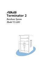
Terminator 2
Barebone System
Model T2-AH1