Asus T2-AH1 T2-AH1 English user manual E2065 - Page 19
Internal components
 |
View all Asus T2-AH1 manuals
Add to My Manuals
Save this manual to your list of manuals |
Page 19 highlights
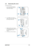
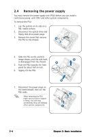
1.5 Internal components The illustration below is the internal view of the system when you remove the top cover and the power supply unit. The installed components are labeled for your reference. Proceed to Chapter 2 for instructions on installing additional system components. 8 9 13 12 14 1 2 11 10 3 4 5 6 15 7 1. Optical drive (optional) 2. 5.25-inch empty optical drive bay 3. Floppy disk drive (optional) 4. Card reader module 5. Front panel cover 6. Hard disk drive metal tray 7. Front panel I/O board 8. Chassis fan 9. ASUS motherboard 10. CPU socket 11. DIMM sockets 12. Expansion slots 13. PCI Express™ x16 slot for discrete graphics card 14. PCI slot 15. Serial ATA connectors ASUS T2-AH1 1-9
-
 1
1 -
2
-
3
-
4
-
5
-
6
-
7
-
8
-
9
-
10
-
11
-
12
-
13
-
 14
14 -
 15
15 -
 16
16 -
 17
17 -
 18
18 -
 19
19 -
 20
20 -
 21
21 -
 22
22 -
 23
23 -
 24
24 -
25
-
26
-
27
-
28
-
29
-
30
-
31
-
32
-
33
-
34
-
35
-
36
-
37
-
38
-
39
-
40
-
41
-
42
-
43
-
44
-
45
-
46
-
47
-
48
-
49
-
50
-
51
-
52
-
53
-
54
-
55
-
56
-
57
-
58
-
59
-
60
-
61
-
62
-
63
-
64
-
65
-
66
-
67
-
68
-
69
-
70
-
71
-
72
-
73
-
74
-
75
-
76
-
77
-
78
-
79
-
80
-
81
-
82
-
83
-
84
-
85
-
86
-
87
-
88
-
89
-
90
-
91
-
92
-
93
-
94
-
95
-
96
-
97
-
98
-
99
-
100
-
101
-
102
-
103
-
104
-
105
-
106
-
107
-
108
-
109
-
110
-
111
-
112
-
113
-
114
-
115
-
116
-
117
-
118
-
119
-
120
-
121
-
122
 |
 |

1-9
1-9
1-9
1-9
1-9
ASUS T2-AH1
ASUS T2-AH1
ASUS T2-AH1
ASUS T2-AH1
ASUS T2-AH1
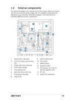
1.
Optical drive
(optional)
2.
5.25-inch empty optical drive
bay
3.
Floppy disk drive
(optional)
4.
Card reader module
5.
Front panel cover
6.
Hard disk drive metal tray
7.
Front panel I/O board
8.
Chassis fan
1.5
Internal components
The illustration below is the internal view of the system when you remove
the top cover and the power supply unit. The installed components are
labeled for your reference. Proceed to Chapter 2 for instructions on
installing additional system components.
3
2
5
6
1
11
9
15
10
8
12
14
4
7
13
9.
ASUS motherboard
10.
CPU socket
11.
DIMM sockets
12.
Expansion slots
13.
PCI Express™ x16 slot for
discrete graphics card
14.
PCI slot
15.
Serial ATA connectors