Asus V7-P8H77E V7-P8H77E User's Manual - Page 18
Internal components
 |
View all Asus V7-P8H77E manuals
Add to My Manuals
Save this manual to your list of manuals |
Page 18 highlights
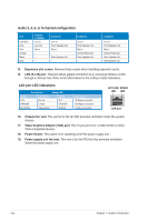
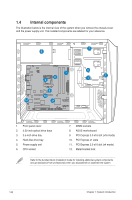
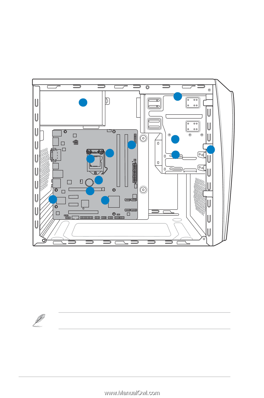
1.4 Internal components The illustration below is the internal view of the system when you remove the chassis cover and the power supply unit. The installed components are labeled for your reference. 2 5 7 6 8 9 10 12 11 3 1 4 1. Front panel cover 2. 5.25-inch optical drive bays 3. 3.5-inch drive bay 4. Hard disk drive bay 5. Power supply unit 6. CPU socket 7. DIMM sockets 8. ASUS motherboard 9. PCI Express 3.0 x16 slot (x16 mode) 10. PCI Express x1 slots 11. PCI Express 2.0 x16 slot (x4 mode) 12. Metal bracket lock Refer to the bundled Quick Installation Guide for installing additional system components and get assistance from professionals when you disassemble or assemble the system. 1-8 Chapter 1: System introduction
-
 1
1 -
2
-
3
-
4
-
5
-
6
-
7
-
8
-
9
-
10
-
11
-
12
-
 13
13 -
 14
14 -
 15
15 -
 16
16 -
 17
17 -
 18
18 -
 19
19 -
 20
20 -
 21
21 -
 22
22 -
 23
23 -
24
-
25
-
26
-
27
-
28
-
29
-
30
-
31
-
32
-
33
-
34
-
35
-
36
-
37
-
38
-
39
-
40
-
41
-
42
-
43
-
44
-
45
-
46
-
47
-
48
-
49
-
50
-
51
-
52
-
53
-
54
-
55
-
56
-
57
-
58
-
59
-
60
-
61
-
62
-
63
-
64
-
65
-
66
-
67
-
68
-
69
-
70
-
71
-
72
-
73
-
74
-
75
-
76
-
77
-
78
-
79
-
80
-
81
-
82
-
83
-
84
-
85
-
86
-
87
-
88
-
89
-
90
 |
 |
1-8
Chapter 1: System introduction
1.4
Internal components
The illustration below is the internal view of the system when you remove the chassis cover
and the power supply unit. The installed components are labeled for your reference.
1.
Front panel cover
2.
5.25-inch optical drive bays
3.
3.5-inch drive bay
4.
Hard disk drive bay
5.
Power supply unit
6.
CPU socket
7.
DIMM sockets
8.
ASUS motherboard
9.
PCI Express 3.0 x16 slot (x16 mode)
10.
PCI Express x1 slots
11.
PCI Express 2.0 x16 slot (x4 mode)
12.
Metal bracket lock
Refer to the bundled Quick Installation Guide for installing additional system components
and get assistance from professionals when you disassemble or assemble the system.
1
4
2
3
5
6
7
8
9
10
12
11