Campbell Scientific IRGASON IRGASON Integrated CO2/H2O Open-Path Gas Analyzer - Page 25
Settings
 |
View all Campbell Scientific IRGASON manuals
Add to My Manuals
Save this manual to your list of manuals |
Page 25 highlights
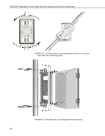
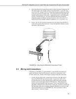
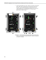
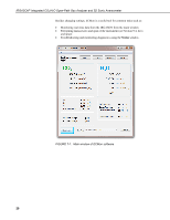
IRGASON® Integrated CO2/H2O Open-Path Gas Analyzer and 3D Sonic Anemometer 7. Settings o Analog output: use cable CABLE4CBL-L (pn 21972) or CABLE2TP-L (pn 26986-L). Once again, the customer specifies the length of this cable at time of order. The connector labeled Analog Outputs on the EC100 panel indicates where each wire should be connected (CO2 voltage signal, H2O voltage signal, and two ground connections). 6. Wire power and ground (i.e., power reference) cable CABLEPCBL-L (pn 21969-L) to the EC100. Feed the cable through one of the cable port openings in the base of the EC100 enclosure and attach the ends into the green EC100 power connector (pn 3768). Plug the connector into the female power connector on the EC100 panel. Ensure that the power and ground ends are going to the appropriate terminals labeled 12V and ground, respectively. 7. Connect the power cable to a power source. The power and ground ends may be wired to the 12V and G ports, respectively, of a Campbell Scientific datalogger or to another 12 Vdc source. 8. Once power is applied to the EC100, three status LEDs on the EC100 panel will illuminate. The power LED is green and the sonic and gas LEDs are orange until the unit has warmed up and is ready to make measurements at which time the LEDs become green. If, after several minutes, the LEDs turn red, a diagnostic flag has been detected. Check the individual diagnostic bits to determine the specific fault. Diagnostics may be monitored using the Status Window of ECMon, the user interface software included with the IRGASON (see Section 7, Settings), or with a datalogger (see Section 10, Datalogger Programming). The diagnostics may reveal that the unit needs service such as cleaning the optical windows on the gas analyzer, clear the sonic transducers of ice or debris, etc. (see Section 9, Maintenance). Operation of the IRGASON can be customized by changing settings. Factory defaults work well for most applications, but the user may adjust the settings with a PC using either the Campbell Scientific ECMon software (see Section 7.14, ECMon) or DevConfig (see Section 7.15, Device Configuration Utility), or with a datalogger using the EC100Configure() instruction (see Section 10.2, EC100Configure() Instruction). 15
-
 1
1 -
2
-
3
-
4
-
5
-
6
-
7
-
8
-
9
-
10
-
11
-
12
-
13
-
14
-
15
-
16
-
17
-
18
-
19
-
 20
20 -
 21
21 -
 22
22 -
 23
23 -
 24
24 -
 25
25 -
 26
26 -
 27
27 -
 28
28 -
 29
29 -
 30
30 -
31
-
32
-
33
-
34
-
35
-
36
-
37
-
38
-
39
-
40
-
41
-
42
-
43
-
44
-
45
-
46
-
47
-
48
-
49
-
50
-
51
-
52
-
53
-
54
-
55
-
56
-
57
-
58
-
59
-
60
-
61
-
62
-
63
-
64
-
65
-
66
 |
 |