Campbell Scientific IRGASON IRGASON Integrated CO2/H2O Open-Path Gas Analyzer - Page 36
PN 28902 CSAT3 Sonic Wick Spares Kit contents, Wick Spares Kit pn 28902.
 |
View all Campbell Scientific IRGASON manuals
Add to My Manuals
Save this manual to your list of manuals |
Page 36 highlights
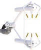
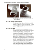
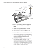
IRGASON® Integrated CO2/H2O Open-Path Gas Analyzer and 3D Sonic Anemometer Wick Spares Kit (pn 28902) consists of three top wicks, three bottom wicks, adhesive, and an installation tool (see FIGURE 9-2). The installation tool is used by placing a wick over the angled end of the tool, placing the straight end of the tool gently against the transducer face, and sliding the wick down the tool onto the transducer. When installing wicks, be sure they are located in the proper position. The top wick must be flush with the transducer face, with the wick tail located at the lowest point of the transducer (see FIGURE 9-1). The end of the bottom transducer wick must extend above the transducer face by one-half to one mesh line (see FIGURE 9-1). Secure the wicks to the transducer with a drop of adhesive which is provided in the CSAT3 Sonic Wick Spares Kit (pn 28902). Take care that the adhesive is not deposited on the transducer face. FIGURE 9-1. Proper location of the sonic top wick (left) and bottom wick (right) FIGURE 9-2. PN 28902 CSAT3 Sonic Wick Spares Kit contents 26
-
 1
1 -
2
-
3
-
4
-
5
-
6
-
7
-
8
-
9
-
10
-
11
-
12
-
13
-
14
-
15
-
16
-
17
-
18
-
19
-
20
-
21
-
22
-
23
-
24
-
25
-
26
-
27
-
28
-
29
-
30
-
 31
31 -
 32
32 -
 33
33 -
 34
34 -
 35
35 -
 36
36 -
 37
37 -
 38
38 -
 39
39 -
 40
40 -
 41
41 -
42
-
43
-
44
-
45
-
46
-
47
-
48
-
49
-
50
-
51
-
52
-
53
-
54
-
55
-
56
-
57
-
58
-
59
-
60
-
61
-
62
-
63
-
64
-
65
-
66
 |
 |
