Campbell Scientific IRGASON IRGASON Integrated CO2/H2O Open-Path Gas Analyzer - Page 39
CAUTION, evaporate from the analyzer before proceeding with
 |
View all Campbell Scientific IRGASON manuals
Add to My Manuals
Save this manual to your list of manuals |
Page 39 highlights
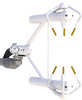
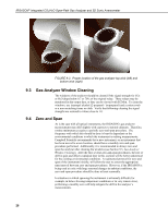
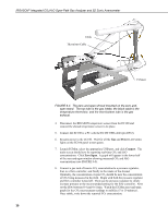
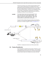
IRGASON® Integrated CO2/H2O Open-Path Gas Analyzer and 3D Sonic Anemometer CAUTION CAUTION The first part of the following procedure simply measures the CO2 and H2O zero and span, without making adjustments. This allows the CO2 and H2O gain factors to be calculated. These gain factors quantify the state of the analyzer before the zero-and-span procedure, and in theory could be used to correct recent measurements for drift. The last part of the zero-and-span procedure adjusts internal processing parameters to correct subsequent measurements. If the zero-and-span procedure is being performed off-site (e.g., in a lab), be sure to mount the IRGASON on the lab stand (pn 27278). This will ensure the analyzer is in the correct upright orientation and has the correct optical alignment. It is imperative that the zero-and-span procedure be done correctly and not rushed; allocate plenty of time for the procedure (at least an hour). Resting the analyzer on its side during the zero-and-span procedure may result in measurement inaccuracy. To check and then set the IRGASON zero and span, follow the steps below: 1. Remove power from the EC100. 2. If not already done, clean the windows and snouts with alcohol and a nonscratching tissue or cloth. Make sure the alcohol and any residual water completely evaporate from the analyzer before proceeding with the zero-and-span procedure. 3. As shown in FIGURE 9-4, position the IRGASON zero-and-span shroud (pn 26390) over the upper and lower snouts. To do this, twist the two ends of the shroud together to minimize the length of the shroud. Make sure the rubber seals on the ends of the shroud are clean and in good condition. Position one end of the shroud over the lower snout and twist the top part of the shroud, allowing it to extend and cover the upper snout; while doing so, avoid making contact with the sonic transducers. Continue twisting the shroud until it is fully extended and covering both snouts. Twist the shroud so that the gas tubes and temperature thermistor cable are directed towards the back of the sensor. Hang the tubes and cable over the trunk of the sensor to alleviate any strain on the optical arms. See FIGURE 9-4, The zero-and-span shroud mounted on the zero-and-span stand. 29
-
 1
1 -
2
-
3
-
4
-
5
-
6
-
7
-
8
-
9
-
10
-
11
-
12
-
13
-
14
-
15
-
16
-
17
-
18
-
19
-
20
-
21
-
22
-
23
-
24
-
25
-
26
-
27
-
28
-
29
-
30
-
31
-
32
-
33
-
 34
34 -
 35
35 -
 36
36 -
 37
37 -
 38
38 -
 39
39 -
 40
40 -
 41
41 -
 42
42 -
 43
43 -
 44
44 -
45
-
46
-
47
-
48
-
49
-
50
-
51
-
52
-
53
-
54
-
55
-
56
-
57
-
58
-
59
-
60
-
61
-
62
-
63
-
64
-
65
-
66
 |
 |
