Canon VB-S900F User Manual - Page 103
Setting Intelligent Function Detection Settings, Setting Detection Criteria [Detection, Criteria] tab
 |
View all Canon VB-S900F manuals
Add to My Manuals
Save this manual to your list of manuals |
Page 103 highlights
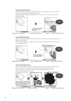
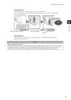
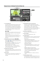
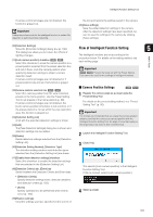
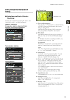
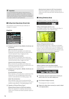
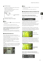
Setting Intelligent Function Detection Settings „ Setting Detection Criteria ([Detection Criteria] tab) Set detection criteria while operating the camera and checking the video in the video display area. [Detection Criteria] tab Moving object detection, abandoned object detection, camera tampering detection (1) (2) (3) (4) Removed object detection (1) (2) (3) (4) Passing detection (1) (5) (3) (6) (7) (4) Intelligent Function Setting Tool Video Display Area Detection Area (1) [Detection Settings Name] 5 You can use up to 64 characters in a detection setting Admin Tools name. Be sure to enter a single-byte alphanumeric detection setting name. In a [Detection Settings Name], ASCII characters (spaces or printable characters) can be used. (2) [Area Shape] Select [Rectangular] or [Polygonal] for the shape of detection areas you want to set in the video display area. For details on detection area setting operations, see "Setting Detection Areas" (p. 104). [Quick setting] The detection area is drawn automatically when the detection criteria is [Removed Object Detection]. [Clear] If the [Area Shape] is [Polygonal], the detection area set in the video display area is deleted. (3) [Display Color] Choose the color of the detection setting. The color selected here becomes the display color of the detection area/line in the video display area. (4) [Object Size (%)] [Change Ratio (%)] [Duration (Sec)] Set the lower limit for the size, change ratio, and judgment time for the set detection area to trigger detection. If the value set here is exceeded, "Detected" mode is triggered. Click the text box to enter a value directly, or specify a value using the slider. For details on the setting method, see "Setting Detection Criteria per Detection Type" (p. 105). (5) [Clear detection line] Clears the detection line set in the video display area. (6) [Passing Direction] Select the passing direction of a moving object relative to the detection line. (7) [Decision Point] Select the point of a moving object that will be used as criteria for passing detection when a moving object crosses a detection line. 103
-
 1
1 -
2
-
3
-
4
-
5
-
6
-
7
-
8
-
9
-
10
-
11
-
12
-
13
-
14
-
15
-
16
-
17
-
18
-
19
-
20
-
21
-
22
-
23
-
24
-
25
-
26
-
27
-
28
-
29
-
30
-
31
-
32
-
33
-
34
-
35
-
36
-
37
-
38
-
39
-
40
-
41
-
42
-
43
-
44
-
45
-
46
-
47
-
48
-
49
-
50
-
51
-
52
-
53
-
54
-
55
-
56
-
57
-
58
-
59
-
60
-
61
-
62
-
63
-
64
-
65
-
66
-
67
-
68
-
69
-
70
-
71
-
72
-
73
-
74
-
75
-
76
-
77
-
78
-
79
-
80
-
81
-
82
-
83
-
84
-
85
-
86
-
87
-
88
-
89
-
90
-
91
-
92
-
93
-
94
-
95
-
96
-
97
-
 98
98 -
 99
99 -
 100
100 -
 101
101 -
 102
102 -
 103
103 -
 104
104 -
 105
105 -
 106
106 -
 107
107 -
 108
108 -
109
-
110
-
111
-
112
-
113
-
114
-
115
-
116
-
117
-
118
-
119
-
120
-
121
-
122
-
123
-
124
-
125
-
126
-
127
-
128
-
129
-
130
-
131
-
132
-
133
-
134
-
135
-
136
-
137
-
138
-
139
-
140
-
141
-
142
-
143
-
144
-
145
-
146
-
147
-
148
-
149
-
150
-
151
-
152
-
153
-
154
-
155
-
156
-
157
-
158
-
159
-
160
-
161
-
162
-
163
-
164
-
165
-
166
-
167
-
168
-
169
-
170
-
171
-
172
-
173
-
174
-
175
-
176
 |
 |
