Cisco ESW-540-48 Administration Guide - Page 28
Scenario 8: Cisco Smart Business Communications System, Configuration, Getting Started - 24 port
 |
UPC - 882658251351
View all Cisco ESW-540-48 manuals
Add to My Manuals
Save this manual to your list of manuals |
Page 28 highlights
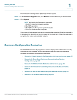
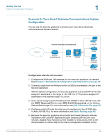
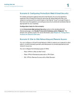
Getting Started Common Configuration Scenarios 1 Scenario 8: Cisco Smart Business Communications System Configuration You can use the security appliance to protect your Cisco Smart Business Communications System network. 235235 Outside Network Private Network Laptop computer Internet Internet Access Device SA 500 UC500 Printer Personal computer IP IP Phone Configuration tasks for this scenario: 1. Configure the WAN and LAN settings for your security appliance, as needed. See Scenario 1: Basic Network Configuration with Internet Access, page 26. 2. Connect a cable from the WAN port of the UC500 to an available LAN port of the security appliance. With the default configuration, the security appliance acts as a DCHP server that assigns IP addresses in the range of 192.168.75.x. IP Phones are assigned IP addresses in the address range 10.1.1.x/24. 3. If you want to assign a static IP address to the UC500 or other LAN devices, click the DHCP Reserved IPs link under WAN & LAN Connectivity on the Getting Started (Basic) page. For more information, see DHCP Reserved IPs, page 52. 4. Configure a static IP route from the security appliance to the UC 500 data VLANs (192.168.10.x). For more information, see Static Routing, page 68. 5. Because the security appliance will provide the firewall, Network Address Translation (NAT), and SIP Application Layer Gateway (SIP-ALG) for your network, disable those functions on the UC500. For instructions, refer to the documentation or online Help for the Cisco Configuration Assistant (CCA). Cisco SA500 Series Security Appliances Administration Guide 28
-
 1
1 -
2
-
3
-
4
-
5
-
6
-
7
-
8
-
9
-
10
-
11
-
12
-
13
-
14
-
15
-
16
-
17
-
18
-
19
-
20
-
21
-
22
-
 23
23 -
 24
24 -
 25
25 -
 26
26 -
 27
27 -
 28
28 -
 29
29 -
 30
30 -
 31
31 -
 32
32 -
 33
33 -
34
-
35
-
36
-
37
-
38
-
39
-
40
-
41
-
42
-
43
-
44
-
45
-
46
-
47
-
48
-
49
-
50
-
51
-
52
-
53
-
54
-
55
-
56
-
57
-
58
-
59
-
60
-
61
-
62
-
63
-
64
-
65
-
66
-
67
-
68
-
69
-
70
-
71
-
72
-
73
-
74
-
75
-
76
-
77
-
78
-
79
-
80
-
81
-
82
-
83
-
84
-
85
-
86
-
87
-
88
-
89
-
90
-
91
-
92
-
93
-
94
-
95
-
96
-
97
-
98
-
99
-
100
-
101
-
102
-
103
-
104
-
105
-
106
-
107
-
108
-
109
-
110
-
111
-
112
-
113
-
114
-
115
-
116
-
117
-
118
-
119
-
120
-
121
-
122
-
123
-
124
-
125
-
126
-
127
-
128
-
129
-
130
-
131
-
132
-
133
-
134
-
135
-
136
-
137
-
138
-
139
-
140
-
141
-
142
-
143
-
144
-
145
-
146
-
147
-
148
-
149
-
150
-
151
-
152
-
153
-
154
-
155
-
156
-
157
-
158
-
159
-
160
-
161
-
162
-
163
-
164
-
165
-
166
-
167
-
168
-
169
-
170
-
171
-
172
-
173
-
174
-
175
-
176
-
177
-
178
-
179
-
180
-
181
-
182
-
183
-
184
-
185
-
186
-
187
-
188
-
189
-
190
-
191
-
192
-
193
-
194
-
195
-
196
-
197
-
198
-
199
-
200
-
201
-
202
-
203
-
204
-
205
-
206
-
207
-
208
-
209
-
210
-
211
-
212
-
213
-
214
-
215
-
216
-
217
-
218
-
219
-
220
-
221
-
222
-
223
-
224
-
225
-
226
-
227
-
228
-
229
-
230
-
231
-
232
-
233
-
234
-
235
-
236
-
237
-
238
-
239
-
240
 |
 |
