D-Link DCS-6511 Product Manual
D-Link DCS-6511 Manual
 |
View all D-Link DCS-6511 manuals
Add to My Manuals
Save this manual to your list of manuals |
D-Link DCS-6511 manual content summary:
- D-Link DCS-6511 | Product Manual - Page 1
- D-Link DCS-6511 | Product Manual - Page 2
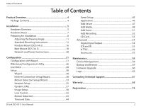
Reset 7 Preparing for Installation 8 Adjusting the Viewing Angle 11 Standard Mounting Instructions 12 Pendant Mount (DCS-34-2 16 Bent Mount (DCS and Date 44 D-Link DCS-6511 User Manual Event Setup 45 Firmware Upgrade 60 Logs 62 Contacting Technical Support 67 Warranty 68 Registration 74 2 - D-Link DCS-6511 | Product Manual - Page 3
or organization of such revisions or changes. Manual Revisions Revision 1.0 Date January 5, 2011 Description DCS-6511 Revision A1 with firmware version 1.00 Trademarks D-Link and the D-Link logo are trademarks or registered trademarks of D-Link Corporation or its subsidiaries in the United - D-Link DCS-6511 | Product Manual - Page 4
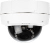
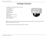
PPraocdkaugcteOCvoenrtveinetws • D-Link DCS-6511 Fixed Dome Network Camera • CAT5 Ethernet Cable • Power Adapter • A/V & Power Cables • Security Wrench • Extension Adapter • Cable Cover • Mounting Bracket and Screws • Rubber Plug • Manual and Software on CD • Quick Install Guide Note: Using - D-Link DCS-6511 | Product Manual - Page 5
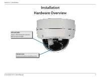
Section 2 - Installation Installation Hardware Overview Infrared LEDs Used to illuminate the camera's field of view at night Camera Lens Motorized varifocal autofocus lens D-Link DCS-6511 User Manual 5 - D-Link DCS-6511 | Product Manual - Page 6
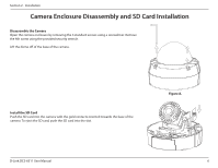
using the provided security wrench. Lift the dome off of the base of the camera. Install the SD Card Push the SD card into the camera with the gold contacts oriented towards the base of the camera. To eject the SD card, push the SD card into the slot. Figure A. D-Link DCS-6511 User Manual 6 - D-Link DCS-6511 | Product Manual - Page 7
may use the hardware reset button located on the bottom of the camera apparatus to reset the camera to factory default settings. Press and hold the reset button for approximately 10 seconds to reset the camera. Reset Button Resets camera to factory default settings D-Link DCS-6511 User Manual 7 - D-Link DCS-6511 | Product Manual - Page 8
bracket up and off from the camera base. (Figure 1.3) 5. Disconnect the cables from the connectors at the base of the camera. 6. Place the cable into the new hole and reconnect the cables to the cable connectors at the base of the camera. (Figure 1.4) Figure 1.2 D-Link DCS-6511 User Manual 8 - D-Link DCS-6511 | Product Manual - Page 9
and tighten it into place B. Replace the dome enclosure over the IP camera and tighten the 4 screws. Safety Notice: Installation and servicing should be done by certified technicians so as to conform to all local codes and prevent voiding your warranty. Figure 1.3 D-Link DCS-6511 User Manual 9 - D-Link DCS-6511 | Product Manual - Page 10
Figure 1.4 Ethernet Jack RJ-45 connector for Ethernet which can also be used to power the camera using Power over Ethernet (PoE) Audio In Connects to a microphone Audio Out Connects to speakers DI/DO Wiring, 12V DC output I/O connectors for external devices D-Link DCS-6511 User Manual 10 - D-Link DCS-6511 | Product Manual - Page 11
the camera, and turn the lens module up and down until the desired position is achieved; tighten the tilt screws once completed. Turn the lens to adjust the IP camera's image until the desired orientation is achieved. Tighten the image adjustment screw once completed. D-Link DCS-6511 User Manual - D-Link DCS-6511 | Product Manual - Page 12
an access hole in the ceiling for the cables. 6. Drill four separate 6 mm holes corresponding to the holes in the mounting template and insert the plastic anchors into these holes. 7. Attach the surface bracket to the ceiling using the screws provided. Figure 2.1 D-Link DCS-6511 User Manual 12 - D-Link DCS-6511 | Product Manual - Page 13
Ethernet cable and the power cable, threading them through the hole in the ceiling. (Figure 2.2) 2. Push the dome body up over the base of the camera. 3. Attach the dome to the base of the camera using the 3 long screws and the provided security screw. Figure 2.2 D-Link DCS-6511 User Manual 13 - D-Link DCS-6511 | Product Manual - Page 14
of the camera. (Figure 2.3) 3. Thread the cables through the waterproof plugs on the side of the base of the camera. Attach the cables to the corresponding cable connectors. (See page 10.) 4. Attach the dual-holed plate to the base of the camera. (Figure 2.4) Figure 2.3 D-Link DCS-6511 User Manual - D-Link DCS-6511 | Product Manual - Page 15
position on the ceiling for the mounting plate to be installed. 3. Use the mounting template to mark the holes for camera. (Figure 2.6) 7. Attach the dome to the base of the camera using the 3 long screws and the provided security screw. Figure 2.5 Figure 2.6 D-Link DCS-6511 User Manual - D-Link DCS-6511 | Product Manual - Page 16
of the pendant bracket, rotating the cap counterclockwise to tighten it into place. 8. Insert the screw into the base of the pendant bracket at the top of the bracket cap to secure the bracket cap into place. Figure 3.1 Rubber Seal Pendant Bracket D-Link DCS-6511 User Manual Figure 3.2 Bracket - D-Link DCS-6511 | Product Manual - Page 17
cable and the power cable and thread them through the pendant bracket. 10. Place the dome body onto the base of the camera. (Figure 3.3) 11. Attach the dome to the base of the camera using the 3 long screws and the provided security screw. Figure 3.3 D-Link DCS-6511 User Manual Figure 3.4 17 - D-Link DCS-6511 | Product Manual - Page 18
in marking the mounting hole. 3. Cut the hole in the ceiling according to the template Mounting Plate 4. Drill 4 separate 6 mm holes corresponding to the holes in the mounting template and cable and thread them through the pendant bracket. D-Link DCS-6511 User Manual Figure 4.2 Bracket Cap 18 - D-Link DCS-6511 | Product Manual - Page 19
Section 2 - Installation 10. Place the dome body onto the base of the camera. (Figure 4.3) 11. Attach the dome to the base of the camera using the 3 long screws and the provided security screw. Bent Bracket Dome Camera Figure 4.3 D-Link DCS-6511 User Manual Figure 4.4 19 - D-Link DCS-6511 | Product Manual - Page 20
cable from the camera to a power source such as your building's emergency power. Connection with a PoE Hub If you are using a PoE hub, connect the IP camera to the hub via an Ethernet cable, which will provide transmission of both power and data over a single cable. D-Link DCS-6511 User Manual 20 - D-Link DCS-6511 | Product Manual - Page 21
function on your computer is disabled, or if the D-Link Launcher fails to start automatically, click Start > Run. Type D:\autorun.exe, where D: represents the drive letter of your CD-ROM drive. Click Setup Wizard to begin the installation. Click Next to continue. D-Link DCS-6511 User Manual 21 - D-Link DCS-6511 | Product Manual - Page 22
Section 3 - Configuration Click Yes to accept the License Agreement. To start the installation process, click Next. Note: The installation may take several minutes to finish. D-Link DCS-6511 User Manual 22 - D-Link DCS-6511 | Product Manual - Page 23
Section 3 - Configuration Click Finish to complete the installation. Click on the D-Link Setup Wizard SE icon that was created in your Windows Start menu. Start > D-Link > Setup Wizard SE D-Link DCS-6511 User Manual 23 - D-Link DCS-6511 | Product Manual - Page 24
's default static IP address 192.168.0.20 will be displayed. Click the Wizard button to continue. Enter the Admin ID and password. When logging in for the first time, the default Admin ID is admin with the password left blank. Click Next, to proceed to the next page. D-Link DCS-6511 User Manual 24 - D-Link DCS-6511 | Product Manual - Page 25
Select DHCP if your camera obtains an IP address automatically when it boots up. Select Static IP if the camera will use the same IP address each time it is started. Click Next, to proceed to the next page. Take a moment to confirm your settings and click Restart. D-Link DCS-6511 User Manual 25 - D-Link DCS-6511 | Product Manual - Page 26
the camera and click the button labeled "Link" to access the web configuration. The Setup Wizard will automatically open your web browser to the IP address of the camera. Alternatively, you may manually open a browser and enter the IP address of the camera: 192.168.0.20 D-Link DCS-6511 User Manual - D-Link DCS-6511 | Product Manual - Page 27
the password blank. Click OK to continue. This section shows your camera's live video. You can select your video profile and view or operate the camera. For additional information about web configuration, please refer to the user manual included on the CD-ROM or the D-Link website. D-Link DCS-6511 - D-Link DCS-6511 | Product Manual - Page 28
when a trigger event occurs. Recording Indicator Note: The video motion feature for your camera must be enabled. When a recording is in progress, this indicator will change color pan, tilt, and zoom within the camera's predefined view area, if one has been defined. D-Link DCS-6511 User Manual 28 - D-Link DCS-6511 | Product Manual - Page 29
displays the status of your I/O device if a device has been connected. PTZ Control: This camera uses electronic pan/tilt/zoom (ePTZ) to select and view areas of interest Stops the camera ePTZ motion Preset Path Starts the camera's motion along the predefined path D-Link DCS-6511 User Manual 29 - D-Link DCS-6511 | Product Manual - Page 30
Setup Wizard This wizard will guide you through a step-by-step process to configure your new D-Link Camera and connect the camera to the internet. Click Next to continue. Note: Select DHCP if you are unsure of which settings to choose. Click Next to continue. D-Link DCS-6511 User Manual 30 - D-Link DCS-6511 | Product Manual - Page 31
password, otherwise click Next to continue. If you have a Dynamic DNS account and would like the camera to update your IP address automatically, Select Enable DDNS and enter your host information. Click Next to continue. Enter a name for your camera and click Next to continue. D-Link DCS-6511 User - D-Link DCS-6511 | Product Manual - Page 32
scheduled. Click Next to continue. If you have selected DHCP, you will see a summary of your settings, including the camera's IP address. Please write down all of this information as you will need it in order to access your camera. Click Apply to save your settings. D-Link DCS-6511 User Manual 32 - D-Link DCS-6511 | Product Manual - Page 33
Section 3 - Configuration Motion Detection Setup Wizard This wizard will guide you through a step-by-step process to configure your camera's motion detection functions. Click Next to continue. Step 1 the day and hours. You may also choose to always record motion. D-Link DCS-6511 User Manual 33 - D-Link DCS-6511 | Product Manual - Page 34
This step allows you to specify how you will receive event notifications from your camera. You may choose not to receive notifications, or to receive notifications via e-mail to save them. Please wait a few moments while the camera saves your settings and restarts. D-Link DCS-6511 User Manual 34 - D-Link DCS-6511 | Product Manual - Page 35
DNS. Enable UPnP: Enabling this setting allows your camera to be configured as a UPnP device on your network. Enable UPnP Port Enabling this setting allows the camera to add port forwarding entries into the router automatically on a UPnP capable Forwarding: network. D-Link DCS-6511 User Manual 35 - D-Link DCS-6511 | Product Manual - Page 36
be useful when connecting your device to a busy or heavily loaded network. Entering a value of '0' indicates that the camera should not monitor bandwidth. Specifying other values will limit the camera's transfer speed to the specified number of Kilobytes per second. D-Link DCS-6511 User Manual 36 - D-Link DCS-6511 | Product Manual - Page 37
. User Name: Enter your user name or e-mail used to connect to the DDNS. Password: Enter your password used to connect to the DDNS server. Timeout: Enter DNS Timeout values. Status: Indicates the connection status, which is automatically determined by the system. D-Link DCS-6511 User Manual 37 - D-Link DCS-6511 | Product Manual - Page 38
over the camera image to draw a mask area. Right clicking on the camera image brings up the following menu options: Disable All: Disables all mask areas Enable All: Enables all mask areas Reset All: AGC value. To reduce sharpness and noise, use a lower AGC value. D-Link DCS-6511 User Manual 38 - D-Link DCS-6511 | Product Manual - Page 39
applied to the image. WDR Level: This option allows the camera to operate in environments with high-contrast such as lobby entrances, parking lots, ATMs, loading areas, and more. You may adjust the level from 0 to 8 depending on your particular application. D-Link DCS-6511 User Manual 39 - D-Link DCS-6511 | Product Manual - Page 40
rates will result in stuttering motion. The maximum number of frames that is displayed in 1 second. 30 fps is the highest video quality for this camera. In general, any frame rate above 15 fps is imperceptible to the human eye. D-Link DCS-6511 User Manual 40 - D-Link DCS-6511 | Product Manual - Page 41
bandwidth. Constant Bit Rate: The bps will affect the bit rate of the video recorded by the camera. Higher bit rates result in higher video quality. JPEG Quality: Select the image quality level of JPEG a level between 1 (lowest) and 10 (highest) for the audio out. D-Link DCS-6511 User Manual 41 - D-Link DCS-6511 | Product Manual - Page 42
the focus using the focus slider. Lens Zoom Speed: Select a speed between 1 and 10 for the camera's optical zoom feature. Zoom: Use the slider bar to adjust the zoom level. Focus: When Manual focus is selected, you may use this slider bar to adjust the focus level. D-Link DCS-6511 User Manual 42 - D-Link DCS-6511 | Product Manual - Page 43
clicking on the camera image brings up the following menu options: Select All: Draws a motion detection area over the entire screen. Clear All: Clears any motion detection areas that have been drawn. Restore: Restores the previously specified motion detection areas. D-Link DCS-6511 User Manual 43 - D-Link DCS-6511 | Product Manual - Page 44
DCS-6511 with an Internet time server. Choose the one that is closest to your location. Set the Date and Time This option allows you to set the time and date manually. Manually: Copy Your Computer's This will synchronize the time information from your PC. Time Settings: D-Link DCS-6511 User Manual - D-Link DCS-6511 | Product Manual - Page 45
. 3. Click on the item name to pop up a window for modifying. Note: You can add up to four events, five servers, and five media fields. D-Link DCS-6511 User Manual 45 - D-Link DCS-6511 | Product Manual - Page 46
Application In a typical application, when motion is detected, the DCS-6511 Network Camera sends images to a FTP server or via e-mail as notifications media columns first so that the Network Camera will know what action shall be performed when a trigger is activated. D-Link DCS-6511 User Manual 46 - D-Link DCS-6511 | Product Manual - Page 47
e-mail server account. FTP: Enter the configuration for the target FTP server account. Network Storage: Specify a network storage device. Only one network storage device is supported. SD Card: Use the camera's onboard SD card storage. D-Link DCS-6511 User Manual 47 - D-Link DCS-6511 | Product Manual - Page 48
prefix: The prefix name will be added on the file name of the video clip. System log: Select this option to save events to the camera system log. D-Link DCS-6511 User Manual 48 - D-Link DCS-6511 | Product Manual - Page 49
prefix Date and time suffix The format is: YYYYMMDD_HHMMSS Maximum duration Specify the maximal recording duration in seconds. You can set up to ten seconds. D-Link DCS-6511 User Manual 49 - D-Link DCS-6511 | Product Manual - Page 50
: If the Pre-event recording is set to five seconds and the Maximum duration is set to ten seconds, the Network Camera continues to record for another four seconds after a trigger is activated. 1 sec. 2 sec. 3 sec. 4 sec. and time suffix The format is: YYYYMMDD_HHMMSS D-Link DCS-6511 User Manual 50 - D-Link DCS-6511 | Product Manual - Page 51
Lost: Triggers an event when the network is lost. Time: Select Always or enter the time interval. Trigger D/O: Select to trigger the digital output for a specific number of seconds when an event occurs. D-Link DCS-6511 User Manual 51 - D-Link DCS-6511 | Product Manual - Page 52
For example, if each recording file is 6MB, and the total cyclic recording size is 600MB, then the camera will record 100 files in the specified location (folder) and then will delete the oldest file and create will be added on the file name of the recording file(s). D-Link DCS-6511 User Manual 52 - D-Link DCS-6511 | Product Manual - Page 53
the video folder Video: and choose the video file you would like to view. Refresh: Reloads the file and folder information from the SD card. D-Link DCS-6511 User Manual 53 - D-Link DCS-6511 | Product Manual - Page 54
once triggered, images will be taken and e-mailed. Select D/I or D/O Mode: The camera will send a signal when an event is triggered, depending upon the type of device connected on the side of the camera. Video Output: Enable/ disable the BNC terminal TV output signal. D-Link DCS-6511 User Manual 54 - D-Link DCS-6511 | Product Manual - Page 55
, the camera uses Day specific application. Off: The IR light will always be off. On: The IR light will always be on. Sync: The IR light will turn on when the ICR sensor is on. Schedule: The IR light will turn on or off according to the schedule that you specify below. D-Link DCS-6511 User Manual - D-Link DCS-6511 | Product Manual - Page 56
certificate manually Create a certificate request and install Status: Displays the status of the certificate. Note: The certificate cannot be removed while the HTTPS is still enabled. To remove the certificate you must first uncheck Enable HTTPS secure connection. D-Link DCS-6511 User Manual 56 - D-Link DCS-6511 | Product Manual - Page 57
List is set from 1.1.1.0 to 192.255.255.255 and the range of the Denied List is set from 1.1.1.0 to 170.255.255.255. Only users with IPs located between 171.0.0.0 and 192.255.255.255 can access the Network Camera. D-Link DCS-6511 User Manual Alowed List Denied List 57 - D-Link DCS-6511 | Product Manual - Page 58
file name prefix when creating a snapshot or a video clip. Enable OSD: Select this option to enable the On-Screen Display feature for your camera. Label: Enter a label for the camera. Show Time: Select this option to enable the time-stamp display on the video screen. D-Link DCS-6511 User Manual 58 - D-Link DCS-6511 | Product Manual - Page 59
and Drive: then restore the pre-defined settings to your camera by clicking Load Configuration. Restore to Factory You may reset your camera and restore the factory settings Default: by clicking Restore Factory Defaults. Reboot Device: This will restart your camera. D-Link DCS-6511 User Manual 59 - D-Link DCS-6511 | Product Manual - Page 60
Upgrade The camera's current firmware version will be displayed on this screen. You may visit the D-Link Support Website to check for the latest available firmware version. To upgrade the firmware on your DCS-6511, please download and save the latest firmware version from the D-Link Support Page to - D-Link DCS-6511 | Product Manual - Page 61
Section 3 - Configuration Status Device Info This page displays detailed information about your device and network connection. D-Link DCS-6511 User Manual 61 - D-Link DCS-6511 | Product Manual - Page 62
Section 3 - Configuration Logs This page displays the log information of your camera. You may download the information by clicking Download. You may also click Clear to delete the saved log information. D-Link DCS-6511 User Manual 62 - D-Link DCS-6511 | Product Manual - Page 63
Section 3 - Configuration Help This page provides helpful information regarding camera operation. D-Link DCS-6511 User Manual 63 - D-Link DCS-6511 | Product Manual - Page 64
Section 4 - Appendix DI/DO Schematics D-Link DCS-6511 User Manual 64 - D-Link DCS-6511 | Product Manual - Page 65
Technical Specifications Technical Specifications GENERAL SPECIFICATION • 1/3" Megapixel WDR Progressive Scan CMOS • WDR DHCP, ARP, DNS, TCP/IP, DDNS (D-Link), HTTP, HTTPS, UPnP™ Port Forwarding, Samba, SMTP, PPPoE, NTP (D-Link), FTP, RTP, RTSP, UDP CODECS • G.726 D-Link DCS-6511 User Manual 65 - D-Link DCS-6511 | Product Manual - Page 66
Specifications POWER INPUT • 12 V DC 1.25 A • 24 V AC • 802.3af PoE PHYSICAL AND ENVIRONMENTAL • IP-66 weather-proof standard • IK-10 vandal-proof standard • Built-in heater and fan WEIGHT • 1030.5 g STANDARD MOUNTING D-Link DCS-6511 User Manual MOUNTING ACCESSORIES (NOT INCLUDED WITH CAMERA) DCS-34 - D-Link DCS-6511 | Product Manual - Page 67
asked questions and answers to technical issues. For customers within the United States: Phone Support: (877) 354-6555 Internet Support: http://support.dlink.com For customers within Canada: Phone Support: (877) 354-6560 Internet Support: http://support.dlink.ca D-Link DCS-6511 User Manual 67 - D-Link DCS-6511 | Product Manual - Page 68
the defective Hardware will be refunded by D-Link upon return to D-Link of the defective Hardware. All Hardware or part thereof that is replaced by D-Link, or for which the purchase price is refunded, shall become the property of D-Link upon replacement or refund. D-Link DCS-6511 User Manual 68 - D-Link DCS-6511 | Product Manual - Page 69
Link's option, to replace the non-conforming Software (or defective media) with software that substantially conforms to D-Link's functional specifications for the Software or to refund the portion of the actual purchase price Case ID Number at https:// rma.dlink.com/. D-Link DCS-6511 User Manual 69 - D-Link DCS-6511 | Product Manual - Page 70
any manuals or accessories in the shipping package. DLink will only software, firmware or other products or services provided by anyone other than D-Link; and Products that have been purchased from inventory clearance or liquidation sales or other sales in which D-Link Link DCS-6511 User Manual 70 - D-Link DCS-6511 | Product Manual - Page 71
from D-Link Corporation/D-Link Systems, Inc., as stipulated by the United States Copyright Act of 1976 and any amendments thereto. Contents are subject to change without prior notice. Copyright ©2011 by D-Link Corporation/D-Link Systems, Inc. All rights reserved. D-Link DCS-6511 User Manual 71 - D-Link DCS-6511 | Product Manual - Page 72
in accordance with the instructions, may cause harmful specific channels and/or operational frequency bands are country dependent and are firmware programmed at the factory to match the intended destination. The firmware setting is not accessible by the end user. D-Link DCS-6511 User Manual - D-Link DCS-6511 | Product Manual - Page 73
applicable to products purchased outside the United States, please contact the corresponding local D-Link office. Industry Canada Notice: This device complies with RSS-210 of the Industry per regulations of Industry Canada. The required antenna impedance is 50 ohms. D-Link DCS-6511 User Manual 73 - D-Link DCS-6511 | Product Manual - Page 74
Appendix E - Registration Registration Product registration is entirely voluntary and failure to complete or return this form will not diminish your warranty rights. Version 1.0 January 5, 2011 D-Link DCS-6511 User Manual 74
-
 1
1 -
 2
2 -
 3
3 -
 4
4 -
 5
5 -
 6
6 -
 7
7 -
8
-
9
-
10
-
11
-
12
-
13
-
14
-
15
-
16
-
17
-
18
-
19
-
20
-
21
-
22
-
23
-
24
-
25
-
26
-
27
-
28
-
29
-
30
-
31
-
32
-
33
-
34
-
35
-
36
-
37
-
38
-
39
-
40
-
41
-
42
-
43
-
44
-
45
-
46
-
47
-
48
-
49
-
50
-
51
-
52
-
53
-
54
-
55
-
56
-
57
-
58
-
59
-
60
-
61
-
62
-
63
-
64
-
65
-
66
-
67
-
68
-
69
-
70
-
71
-
72
-
73
-
74
 |
 |