D-Link DCS-6511 Product Manual - Page 18
Bent Mount (DCS-34-3 - pendant mount for
 |
View all D-Link DCS-6511 manuals
Add to My Manuals
Save this manual to your list of manuals |
Page 18 highlights
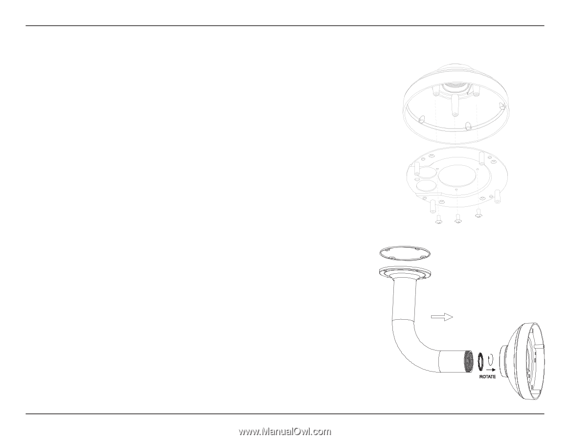
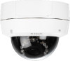
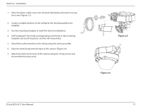
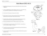
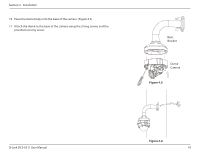
Section 2 - Installation Bent Mount (DCS-34-3) 1. Attach the mounting plate to the bracket cap using the three screws as shown in Figure 4.1. Bracket Cap 2. Locate a suitable position on the ceiling for a 34 mm (+2 / -0 mm) hole to be cut. A template is included to aid in marking the mounting hole. 3. Cut the hole in the ceiling according to the template Mounting Plate 4. Drill 4 separate 6 mm holes corresponding to the holes in the mounting template and insert the plastic anchors into these holes. 5. Place the rubber seal between the bent bracket and the ceiling to ensure a waterproof seal between the ceiling and the bracket. (Figure 4.2) 6. Attach the pendant bracket to the ceiling using the screws provided. 7. Attach the bracket cap to the bottom of the bent bracket, rotating the cap counter-clockwise to tighten it into place. Figure 4.1 Bent Bracket 8. Insert the screw into the base of the bent bracket at the top of the bracket cap to secure the bracket cap into place. 9. Connect the Ethernet cable and the power cable and thread them through the pendant bracket. D-Link DCS-6511 User Manual Figure 4.2 Bracket Cap 18
-
 1
1 -
2
-
3
-
4
-
5
-
6
-
7
-
8
-
9
-
10
-
11
-
12
-
 13
13 -
 14
14 -
 15
15 -
 16
16 -
 17
17 -
 18
18 -
 19
19 -
 20
20 -
 21
21 -
 22
22 -
 23
23 -
24
-
25
-
26
-
27
-
28
-
29
-
30
-
31
-
32
-
33
-
34
-
35
-
36
-
37
-
38
-
39
-
40
-
41
-
42
-
43
-
44
-
45
-
46
-
47
-
48
-
49
-
50
-
51
-
52
-
53
-
54
-
55
-
56
-
57
-
58
-
59
-
60
-
61
-
62
-
63
-
64
-
65
-
66
-
67
-
68
-
69
-
70
-
71
-
72
-
73
-
74
 |
 |