D-Link DGS-3048 Product Manual - Page 16
Rack Installation, Power on, A. Attaching the Mounting Brackets - software
 |
UPC - 790069287367
View all D-Link DGS-3048 manuals
Add to My Manuals
Save this manual to your list of manuals |
Page 16 highlights
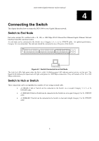
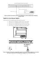
DGS-3048 Gigabit Ethernet Switch Manual Rack Installation The DGS-3048 can be mounted in an EIA standard-sized, 19-inch rack, which can be placed in a wiring closet with other equipment. To install, attach the mounting brackets on the Switch's side panels (one on each side) and secure them with the screws provided. Figure 2- 2A. Attaching the Mounting Brackets Then, use the screws provided with the equipment rack to mount the witch on the rack. Figure 2- 2B. Installing in an Equipment Rack Power on The Switch can be used with AC power supply 100-240 VAC, 50 - 60 Hz. The Switch's power supply will adjust to the local power source automatically and may be powered on without having any or all LAN segment cables connected. After the Switch is plugged in, the LED indicators should respond as follows: • All LED indicators except console will momentarily blink. This blinking of the LEDs indicates a reset of the system. • The console LED indicator will blink while the Switch loads onboard software and performs a self-test. When the POST is passed, the LED will become dark. If the POST fails, the indicator will light solid amber. This indicator lights solid green when the Switch is being logged-in via out-of-band/local console management through the RS232 console port using a straight-through serial cable. 4
-
 1
1 -
2
-
3
-
4
-
5
-
6
-
7
-
8
-
9
-
10
-
 11
11 -
 12
12 -
 13
13 -
 14
14 -
 15
15 -
 16
16 -
 17
17 -
 18
18 -
 19
19 -
 20
20 -
 21
21 -
22
-
23
-
24
-
25
-
26
-
27
-
28
-
29
-
30
-
31
-
32
-
33
-
34
-
35
-
36
-
37
-
38
-
39
-
40
-
41
-
42
-
43
-
44
-
45
-
46
-
47
-
48
-
49
-
50
-
51
-
52
-
53
-
54
-
55
-
56
-
57
-
58
-
59
-
60
-
61
-
62
-
63
-
64
-
65
-
66
-
67
-
68
-
69
-
70
-
71
-
72
-
73
-
74
-
75
-
76
-
77
-
78
-
79
-
80
-
81
-
82
-
83
-
84
-
85
-
86
-
87
-
88
-
89
-
90
-
91
-
92
-
93
-
94
-
95
-
96
-
97
-
98
-
99
-
100
-
101
-
102
-
103
-
104
-
105
-
106
-
107
-
108
-
109
-
110
-
111
-
112
-
113
-
114
-
115
-
116
-
117
-
118
-
119
-
120
-
121
-
122
-
123
-
124
-
125
-
126
-
127
-
128
-
129
-
130
-
131
-
132
-
133
-
134
-
135
-
136
-
137
-
138
-
139
-
140
-
141
-
142
-
143
-
144
-
145
-
146
-
147
 |
 |
