D-Link DSS-200G-10MP Product Manual - Page 104
Areas of the User Interface, AREA 1, Tools, Surveillance, Standard Mode
 |
View all D-Link DSS-200G-10MP manuals
Add to My Manuals
Save this manual to your list of manuals |
Page 104 highlights
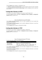
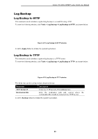
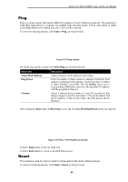
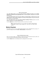
D-Link DSS-200G MP/MPP series Switch User Manual Areas of the User Interface The figure below shows the user interface. Two distinct areas divide the user interface, as described in the table. AREA 3 AREA 1 AREA 2 Figure 5-2 Main Web UI Window Area Number AREA 1 AREA 2 AREA 3 Description The navigation menu is displayed in this area. Click on the links and navigate the folder structure to display information on the main page. This is the main page for displaying information and configuration options for the switch. The page displayed here is based on the selection in AREA 1. This area displays a toolbar used to access Save and Tools menus. It also provides access to the Setup Wizard and selection between Surveillance and Standard Mode. 99
-
 1
1 -
2
-
3
-
4
-
5
-
6
-
7
-
8
-
9
-
10
-
11
-
12
-
13
-
14
-
15
-
16
-
17
-
18
-
19
-
20
-
21
-
22
-
23
-
24
-
25
-
26
-
27
-
28
-
29
-
30
-
31
-
32
-
33
-
34
-
35
-
36
-
37
-
38
-
39
-
40
-
41
-
42
-
43
-
44
-
45
-
46
-
47
-
48
-
49
-
50
-
51
-
52
-
53
-
54
-
55
-
56
-
57
-
58
-
59
-
60
-
61
-
62
-
63
-
64
-
65
-
66
-
67
-
68
-
69
-
70
-
71
-
72
-
73
-
74
-
75
-
76
-
77
-
78
-
79
-
80
-
81
-
82
-
83
-
84
-
85
-
86
-
87
-
88
-
89
-
90
-
91
-
92
-
93
-
94
-
95
-
96
-
97
-
98
-
 99
99 -
 100
100 -
 101
101 -
 102
102 -
 103
103 -
 104
104 -
 105
105 -
 106
106 -
 107
107 -
 108
108 -
 109
109 -
110
-
111
-
112
-
113
-
114
-
115
-
116
-
117
-
118
-
119
-
120
-
121
-
122
-
123
-
124
-
125
-
126
-
127
-
128
-
129
-
130
-
131
-
132
-
133
-
134
-
135
-
136
 |
 |

D-Link DSS-200G MP/MPP series Switch User Manual
99
Areas of the User Interface
The figure below shows the user interface. Two distinct areas divide the user interface, as described
in the table.
Figure 5-2 Main Web UI Window
Area Number
Description
AREA 1
The navigation menu is displayed in this area. Click on the links and navigate the
folder structure to display information on the main page.
AREA 2
This is the main page for displaying information and configuration options for the
switch. The page displayed here is based on the selection in
AREA 1
.
AREA 3
This area displays a toolbar used to access
Save
and
Tools
menus. It also
provides access to the Setup Wizard and selection between
Surveillance
and
Standard Mode
.
AREA 1
AREA 2
AREA 3