D-Link DSS-200G-10MP Product Manual - Page 40
PoE, PoE System, PoE Configuration, System > PoE > PoE Configuration
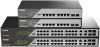 |
View all D-Link DSS-200G-10MP manuals
Add to My Manuals
Save this manual to your list of manuals |
Page 40 highlights
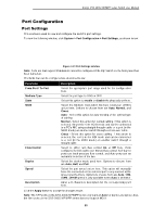
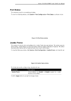
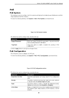
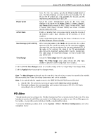
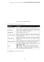
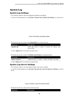
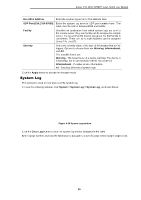
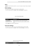
D-Link DSS-200G MP/MPP series Switch User Manual PoE PoE System This window is used to configure the PoE system and display the detailed power information and PoE Trap parameters for PoE modules. To view the following window, click System > PoE > PoE System, as shown below: Figure 4-13 PoE System window The fields that can be configured are described below: Parameter Usage Threshold Trap State Description Enter the usage threshold to generate a log and send the corresponding standard notification. Select this option to enable or disable the sending of PoE notifications. Click the Apply button to accept the changes made. PoE Configuration This window is used to configure the PoE port. To view the following window, click System > PoE > PoE Configuration, as shown below: Figure 4-14 PoE Configuration window The fields that can be configured are described below: Parameter From Port / To Port Priority State 4-Pair State Description Select the appropriate port range used for the configuration here. Select the priority for provisioning power to the port. Options to choose from are Critical, High and Low. Select this option to enable or disable the PoE functionality. Options to choose from are Disabled or Enabled. Enable or disable the 8-core power supply using the 4 pairs of the Ethernet cable: Null, Disabled, 60 W enabled, or 90 W enabled. 35
-
 1
1 -
2
-
3
-
4
-
5
-
6
-
7
-
8
-
9
-
10
-
11
-
12
-
13
-
14
-
15
-
16
-
17
-
18
-
19
-
20
-
21
-
22
-
23
-
24
-
25
-
26
-
27
-
28
-
29
-
30
-
31
-
32
-
33
-
34
-
 35
35 -
 36
36 -
 37
37 -
 38
38 -
 39
39 -
 40
40 -
 41
41 -
 42
42 -
 43
43 -
 44
44 -
 45
45 -
46
-
47
-
48
-
49
-
50
-
51
-
52
-
53
-
54
-
55
-
56
-
57
-
58
-
59
-
60
-
61
-
62
-
63
-
64
-
65
-
66
-
67
-
68
-
69
-
70
-
71
-
72
-
73
-
74
-
75
-
76
-
77
-
78
-
79
-
80
-
81
-
82
-
83
-
84
-
85
-
86
-
87
-
88
-
89
-
90
-
91
-
92
-
93
-
94
-
95
-
96
-
97
-
98
-
99
-
100
-
101
-
102
-
103
-
104
-
105
-
106
-
107
-
108
-
109
-
110
-
111
-
112
-
113
-
114
-
115
-
116
-
117
-
118
-
119
-
120
-
121
-
122
-
123
-
124
-
125
-
126
-
127
-
128
-
129
-
130
-
131
-
132
-
133
-
134
-
135
-
136
 |
 |
