D-Link DSS-200G-10MP Product Manual - Page 26
Step 3: Plugging in the AC Power Cord, Power Failure, Grounding the Switch
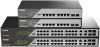 |
View all D-Link DSS-200G-10MP manuals
Add to My Manuals
Save this manual to your list of manuals |
Page 26 highlights
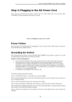
D-Link DSS-200G MP/MPP series Switch User Manual Step 3: Plugging in the AC Power Cord Users may now connect the AC power cord into the rear of the switch and to an electrical outlet (preferably one that is grounded and surge protected). Figure 3-4 Plugging the switch into an outlet Power Failure As a precaution, the switch should be unplugged in case of power failure. When power is resumed, the switch should be plugged back in. Grounding the Switch This section describes how to connect theDSS-200G MP/MPP series switch to ground. You must complete this procedure before powering your switch. Required Tools and Equipment • Ground screws (included in the accessory kit): One M4 x 8 mm (metric) pan-head screw • Ground cable (not included in the accessory kit): The grounding cable should be sized according to local and national installation requirements. Depending on the power supply and system, a 12 to 6 AWG copper conductor is required for U.S installation. Commercially available 6 AWG wire is recommended. The length of the cable depends on the proximity of the switch to proper grounding facilities. • A screwdriver (not included in the accessory kit) Follow these steps to ground the switch: Step 1: Verify that the switch is not connected to a power supply. Step 2: Use the ground cable to place the #8 terminal lug ring on top of the ground-screw opening, as seen in the figure below. Step 3: Insert the ground screw into the ground-screw opening. Step 4: Using a screwdriver, tighten the ground screw to secure the ground cable to the switch. Step 5: Attach the terminal lug ring at the other end of the grounding cable to an appropriate grounding stud or bolt on rack where the switch is installed. Step 6: Verify if the connections at the ground connector on the switch and the rack are securely attached. 21
-
 1
1 -
2
-
3
-
4
-
5
-
6
-
7
-
8
-
9
-
10
-
11
-
12
-
13
-
14
-
15
-
16
-
17
-
18
-
19
-
20
-
 21
21 -
 22
22 -
 23
23 -
 24
24 -
 25
25 -
 26
26 -
 27
27 -
 28
28 -
 29
29 -
 30
30 -
 31
31 -
32
-
33
-
34
-
35
-
36
-
37
-
38
-
39
-
40
-
41
-
42
-
43
-
44
-
45
-
46
-
47
-
48
-
49
-
50
-
51
-
52
-
53
-
54
-
55
-
56
-
57
-
58
-
59
-
60
-
61
-
62
-
63
-
64
-
65
-
66
-
67
-
68
-
69
-
70
-
71
-
72
-
73
-
74
-
75
-
76
-
77
-
78
-
79
-
80
-
81
-
82
-
83
-
84
-
85
-
86
-
87
-
88
-
89
-
90
-
91
-
92
-
93
-
94
-
95
-
96
-
97
-
98
-
99
-
100
-
101
-
102
-
103
-
104
-
105
-
106
-
107
-
108
-
109
-
110
-
111
-
112
-
113
-
114
-
115
-
116
-
117
-
118
-
119
-
120
-
121
-
122
-
123
-
124
-
125
-
126
-
127
-
128
-
129
-
130
-
131
-
132
-
133
-
134
-
135
-
136
 |
 |
