D-Link DSS-200G-10MP Product Manual - Page 12
Rear Panel, DSS-200G-10MPP, Front Panel
 |
View all D-Link DSS-200G-10MP manuals
Add to My Manuals
Save this manual to your list of manuals |
Page 12 highlights
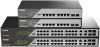
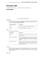
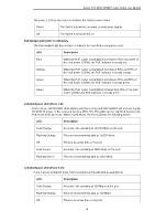
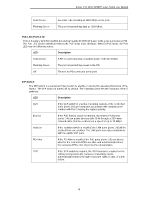
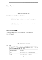
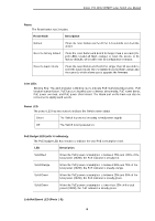
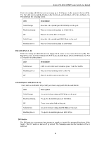
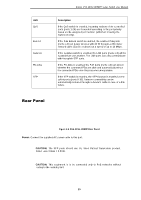
Rear Panel D-Link DSS-200G MP/MPP series Switch User Manual Figure 2-2 DSS-200G-10MP Rear Panel Power: Connect the supplied AC power cable to this port. CAUTION: The SFP ports should use UL listed Optical Transceiver product, Rated Laser Class I. 3.3Vdc. CAUTION: This equipment is to be connected only to PoE networks without routing to the outside plant. DSS-200G-10MPP 8 x 10/100/1000 Mbps PoE ports + 2 x 100/1000 Mbps SFP ports surveillance switch Front Panel Figure 2-3 DSS-200G-10MPP Front Panel Mode Button: By pressing the Mode button over 2 seconds, the Port LED (ports 1~8) will switch between the Link (refer to the below Link/Act/Speed LED) and PoE mode to indicate the PoE ports (refer to the below PoE LED) status or link speed: PoE/Link Mode LED Description Green The Port LED indicator is in Link/Act/Speed mode. Orange The Port LED indicator is in PoE mode. 7
-
 1
1 -
2
-
3
-
4
-
5
-
6
-
 7
7 -
 8
8 -
 9
9 -
 10
10 -
 11
11 -
 12
12 -
 13
13 -
 14
14 -
 15
15 -
 16
16 -
 17
17 -
18
-
19
-
20
-
21
-
22
-
23
-
24
-
25
-
26
-
27
-
28
-
29
-
30
-
31
-
32
-
33
-
34
-
35
-
36
-
37
-
38
-
39
-
40
-
41
-
42
-
43
-
44
-
45
-
46
-
47
-
48
-
49
-
50
-
51
-
52
-
53
-
54
-
55
-
56
-
57
-
58
-
59
-
60
-
61
-
62
-
63
-
64
-
65
-
66
-
67
-
68
-
69
-
70
-
71
-
72
-
73
-
74
-
75
-
76
-
77
-
78
-
79
-
80
-
81
-
82
-
83
-
84
-
85
-
86
-
87
-
88
-
89
-
90
-
91
-
92
-
93
-
94
-
95
-
96
-
97
-
98
-
99
-
100
-
101
-
102
-
103
-
104
-
105
-
106
-
107
-
108
-
109
-
110
-
111
-
112
-
113
-
114
-
115
-
116
-
117
-
118
-
119
-
120
-
121
-
122
-
123
-
124
-
125
-
126
-
127
-
128
-
129
-
130
-
131
-
132
-
133
-
134
-
135
-
136
 |
 |