Dell Alienware Area-51m Service Manual - Page 55
Replacing the display assembly, Procedure
 |
View all Dell Alienware Area-51m manuals
Add to My Manuals
Save this manual to your list of manuals |
Page 55 highlights
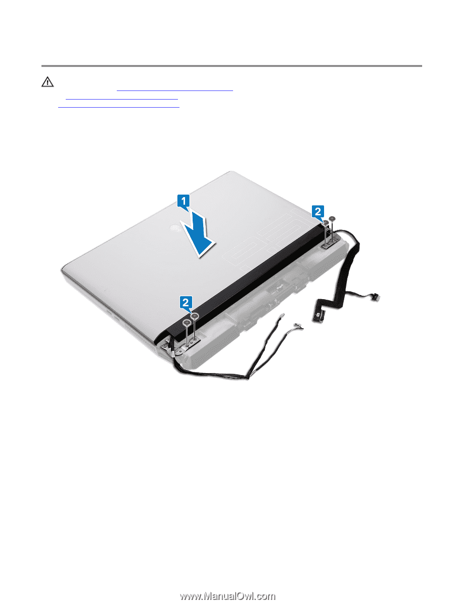
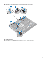
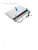
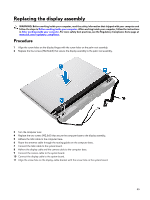
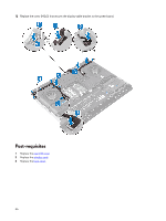
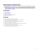
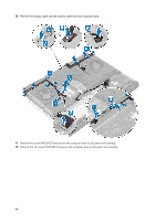
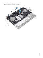
Replacing the display assembly WARNING: Before working inside your computer, read the safety information that shipped with your computer and follow the steps in Before working inside your computer. After working inside your computer, follow the instructions in After working inside your computer. For more safety best practices, see the Regulatory Compliance home page at www.dell.com/regulatory_compliance. Procedure 1 Align the screw holes on the display hinges with the screw holes on the palm-rest assembly. 2 Replace the four screws (M2.5x2.5) that secure the display assembly to the palm-rest assembly. 3 Turn the computer over. 4 Replace the two screws (M2.5x8) that secure the computer base to the display assembly. 5 Adhere the tobii cable to the computer base. 6 Route the antennas cable through the routing guides on the computer base. 7 Connect the tobii cable to the system board. 8 Adhere the display cable and the camera cable to the computer base. 9 Connect the camera cable to the system board. 10 Connect the display cable to the system board. 11 Align the screw hole on the display-cable bracket with the screw hole on the system board. 55
-
 1
1 -
2
-
3
-
4
-
5
-
6
-
7
-
8
-
9
-
10
-
11
-
12
-
13
-
14
-
15
-
16
-
17
-
18
-
19
-
20
-
21
-
22
-
23
-
24
-
25
-
26
-
27
-
28
-
29
-
30
-
31
-
32
-
33
-
34
-
35
-
36
-
37
-
38
-
39
-
40
-
41
-
42
-
43
-
44
-
45
-
46
-
47
-
48
-
49
-
 50
50 -
 51
51 -
 52
52 -
 53
53 -
 54
54 -
 55
55 -
 56
56 -
 57
57 -
 58
58 -
 59
59 -
 60
60 -
61
-
62
-
63
-
64
-
65
-
66
-
67
-
68
-
69
-
70
-
71
-
72
-
73
-
74
-
75
-
76
-
77
-
78
-
79
-
80
-
81
-
82
-
83
-
84
-
85
-
86
-
87
-
88
-
89
-
90
-
91
-
92
-
93
-
94
-
95
-
96
-
97
-
98
-
99
-
100
-
101
-
102
-
103
-
104
-
105
-
106
-
107
-
108
-
109
-
110
-
111
 |
 |