Dell Alienware Area-51m Service Manual - Page 64
Replacing the heat-sink assembly, Procedure
 |
View all Dell Alienware Area-51m manuals
Add to My Manuals
Save this manual to your list of manuals |
Page 64 highlights
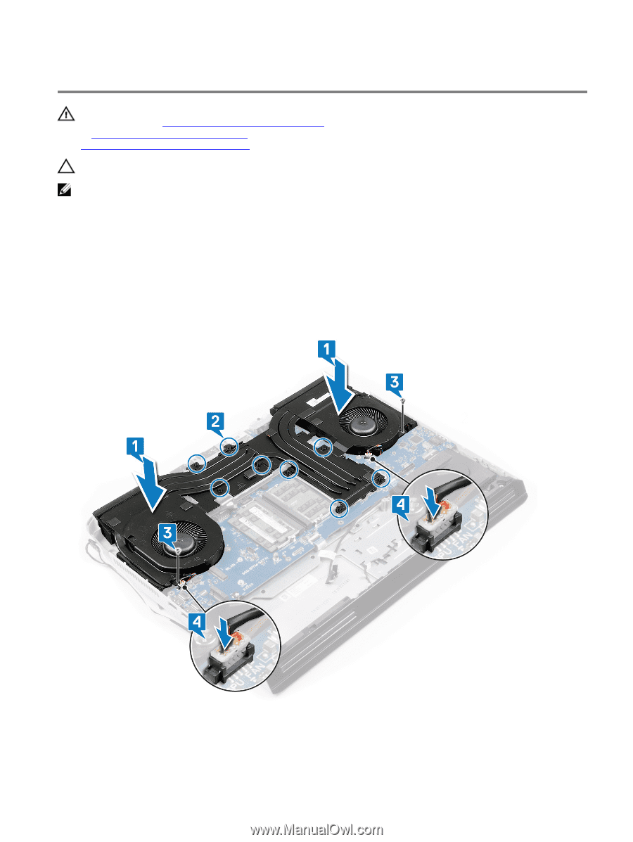
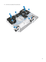
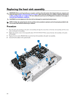
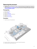
Replacing the heat-sink assembly WARNING: Before working inside your computer, read the safety information that shipped with your computer and follow the steps in Before working inside your computer. After working inside your computer, follow the instructions in After working inside your computer. For more safety best practices, see the Regulatory Compliance home page at www.dell.com/regulatory_compliance. CAUTION: Incorrect alignment of the heat sink can damage the system board and processor. NOTE: If either the system board or the fan and heat-sink assembly is replaced, use the thermal pad provided in the kit to ensure that thermal conductivity is achieved. Procedure 1 Place the heat-sink assembly on the palm-rest assembly and align the screw holes on the heat-sink assembly with the screw holes on the palm-rest assembly. 2 Tighten the captive screws in the sequential order (1>2>3>4>5>6>7>8) to secure the heat-sink assembly to the palmrest assembly. 3 Replace the two screws (M2.5x5) that secure the heat-sink assembly to the palm-rest assembly. 4 Connect the fan cables to the system board. 64
-
 1
1 -
2
-
3
-
4
-
5
-
6
-
7
-
8
-
9
-
10
-
11
-
12
-
13
-
14
-
15
-
16
-
17
-
18
-
19
-
20
-
21
-
22
-
23
-
24
-
25
-
26
-
27
-
28
-
29
-
30
-
31
-
32
-
33
-
34
-
35
-
36
-
37
-
38
-
39
-
40
-
41
-
42
-
43
-
44
-
45
-
46
-
47
-
48
-
49
-
50
-
51
-
52
-
53
-
54
-
55
-
56
-
57
-
58
-
 59
59 -
 60
60 -
 61
61 -
 62
62 -
 63
63 -
 64
64 -
 65
65 -
 66
66 -
 67
67 -
 68
68 -
 69
69 -
70
-
71
-
72
-
73
-
74
-
75
-
76
-
77
-
78
-
79
-
80
-
81
-
82
-
83
-
84
-
85
-
86
-
87
-
88
-
89
-
90
-
91
-
92
-
93
-
94
-
95
-
96
-
97
-
98
-
99
-
100
-
101
-
102
-
103
-
104
-
105
-
106
-
107
-
108
-
109
-
110
-
111
 |
 |