Dell Alienware m15 R7 Service Manual
Dell Alienware m15 R7 Manual
 |
View all Dell Alienware m15 R7 manuals
Add to My Manuals
Save this manual to your list of manuals |
Dell Alienware m15 R7 manual content summary:
- Dell Alienware m15 R7 | Service Manual - Page 1
Alienware m15 R7 Service Manual Regulatory Model: P109F Regulatory Type: P109F005/P109F006 March 2022 Rev. A01 - Dell Alienware m15 R7 | Service Manual - Page 2
of data and tells you how to avoid the problem. WARNING: A WARNING indicates a potential for property damage, personal injury, or death. © 2022 Dell Inc. or its subsidiaries. All rights reserved. Dell, EMC, and other trademarks are trademarks of Dell Inc. or its subsidiaries. Other trademarks may be - Dell Alienware m15 R7 | Service Manual - Page 3
Safety instructions...5 Electrostatic discharge-ESD protection...6 ESD field service kit ...6 Transporting sensitive components...7 After working inside your computer...7 Chapter 2: Removing and installing components 9 Recommended tools...9 Screw list...9 Major components of Alienware m15 R7...10 - Dell Alienware m15 R7 | Service Manual - Page 4
the USB drive in Windows 80 Updating the BIOS from the F12 One-Time boot menu 80 Chapter 5: Troubleshooting...82 Handling swollen Lithium-ion batteries...82 SupportAssist diagnostics...82 System-diagnostic lights...83 Recovering the operating system...84 Backup media and recovery options...84 - Dell Alienware m15 R7 | Service Manual - Page 5
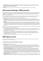
and the contacts. CAUTION: You should only perform troubleshooting and repairs as authorized or directed by the Dell technical assistance team. Damage due to servicing that is not authorized by Dell is not covered by your warranty. See the safety instructions that is shipped with the product or at - Dell Alienware m15 R7 | Service Manual - Page 6
batteries in laptops. Swollen batteries , such as intermittent problems or a shortened product life span. As the industry type of damage to recognize and troubleshoot is the intermittent (also called latent hardware is known as bonding. Use only Field Service kits with a wrist strap, mat, and bonding - Dell Alienware m15 R7 | Service Manual - Page 7
service technicians use the traditional wired ESD grounding wrist strap and protective anti-static mat at all times when servicing Dell stable base, and point your toes out. 2. Tighten stomach muscles. Abdominal muscles support your spine when you lift, offsetting the force of the load. 3. Lift with - Dell Alienware m15 R7 | Service Manual - Page 8
4. Connect your computer and all attached devices to their electrical outlets. 5. Turn on your computer. 8 - Dell Alienware m15 R7 | Service Manual - Page 9
SSD Slot one 2230 or 2280 solid-state drive M2x4 2 in SSD Slot two Wireless-card bracket M2x4 1 Rear I/O cover M2x2 3 Rear I/O cover M2.5x5 2 Battery M2x4 4 Battery M2x3 1 Power-adapter port-bracket M2x4 2 9 - Dell Alienware m15 R7 | Service Manual - Page 10
Rear I/O cover M2.5x2.5 M2x2 M2x2 M2x4 M2x4 M2x2 M2x4 (captive) M2x4 M2x4 M2x4 M2.5x5 Power button M2x2 Quantity 6 2 2 1 2 7 2 6 2 3 2 2 3 Screw image Major components of Alienware m15 R7 The following image shows the major components of - Dell Alienware m15 R7 | Service Manual - Page 11
1. Base cover 2. 2280 solid-state drive thermal shield 3. 2280 solid-state drive 4. 2230 solid-state drive thermal shield 5. 2230 solid-state drive 6. Left fan 11 - Dell Alienware m15 R7 | Service Manual - Page 12
7. Heat sink 8. Right-I/O board 9. Battery 10. Left speaker 11. Palm-rest and keyboard assembly 12. modules 23.Wireless card 24.Wireless-card bracket 25.System board 26.Type-C bracket NOTE: Dell provides a list of components and their part numbers for the original system configuration purchased. - Dell Alienware m15 R7 | Service Manual - Page 13
13 - Dell Alienware m15 R7 | Service Manual - Page 14
14 - Dell Alienware m15 R7 | Service Manual - Page 15
the base cover. 4. Slide and lift the base cover off the palm-rest and keyboard assembly. 5. Peel the tape that secures the battery cable to the battery. 6. Disconnect the battery cable from the system board. 7. Turn over the computer and open the display. 8. Press and hold the power button for 20 - Dell Alienware m15 R7 | Service Manual - Page 16
16 - Dell Alienware m15 R7 | Service Manual - Page 17
board. 2. Adhere the tape that secures the battery cable to the battery. 3. Slide the tabs on the top of The M.2 card installed on M.2 slot one (SSD1) will depend on the configuration ordered. Supported card configurations: ● 2230 solid-state drive ● 2280 solid-state drive The following image(s) - Dell Alienware m15 R7 | Service Manual - Page 18
installation process. About this task NOTE: This procedure applies if you are installing a 2230 solid-state drive into M.2 slot one (SSD1). NOTE: Supported card configurations on M.2 slot one (SSD1): ● 2230 solid-state drive ● 2280 solid-state drive The following image(s) indicate the location of - Dell Alienware m15 R7 | Service Manual - Page 19
-state drive installed in M.2 slot one (SSD1). NOTE: The M.2 card installed on M.2 slot one (SSD1) will depend on the configuration ordered. Supported card configurations: ● 2230 solid-state drive ● 2280 solid-state drive The following image(s) indicate the location of the 2280 solid-state drive in - Dell Alienware m15 R7 | Service Manual - Page 20
installation process. About this task NOTE: This procedure applies if you are installing a 2280 solid-state drive into M.2 slot one (SSD1). NOTE: Supported card configurations on M.2 slot one (SSD1): ● 2230 solid-state drive ● 2280 solid-state drive The following image(s) indicate the location of - Dell Alienware m15 R7 | Service Manual - Page 21
cover. 2. Follow the procedure in After working inside your computer. Procedure to move the screw mount in SSD slot one About this task This computer supports two solid-state drive form factors in SSD slot one: ● M.2 2230 ● M.2 2280 If you are replacing the current solid-state drive in SSD slot one - Dell Alienware m15 R7 | Service Manual - Page 22
solid-state drive installed in M.2 slot two (SSD2). NOTE: The M.2 card installed on M.2 slot two (SSD2) will depend on the configuration ordered. Supported card configurations: ● 2230 solid-state drive ● 2280 solid-state drive NOTE: Only computers shipped with a NVIDIA GeForce 3060/3070 Ti/3080 Ti - Dell Alienware m15 R7 | Service Manual - Page 23
process. About this task NOTE: This procedure applies if you are installing a M.2 2230 solid-state drive into M.2 slot two (SSD2). NOTE: Supported card configurations on M.2 slot two (SSD2): ● M.2 2230 solid-state drive ● M.2 2280 solid-state drive NOTE: You may only install a solid-state - Dell Alienware m15 R7 | Service Manual - Page 24
solid-state drive installed in M.2 slot two (SSD2). NOTE: The M.2 card installed on M.2 slot two (SSD2) will depend on the configuration ordered. Supported card configurations: ● 2230 solid-state drive ● 2280 solid-state drive NOTE: Only computers shipped with a NVIDIA GeForce 3060/3070 Ti/3080 Ti - Dell Alienware m15 R7 | Service Manual - Page 25
process. About this task NOTE: This procedure applies if you are installing a M.2 2280 solid-state drive into M.2 slot two (SSD2). NOTE: Supported card configurations on M.2 slot two (SSD2): ● M.2 2230 solid-state drive ● M.2 2280 solid-state drive NOTE: You may only install a solid-state - Dell Alienware m15 R7 | Service Manual - Page 26
cover. 2. Follow the procedure in After working inside your computer. Procedure to move the screw mount in SSD slot two About this task This computer supports two solid-state drive form factors in SSD slot two: ● M.2 2230 ● M.2 2280 If you are replacing the current solid-state drive in SSD slot two - Dell Alienware m15 R7 | Service Manual - Page 27
3. To install a 2230 solid-state drive in SSD slot two, see installing the 2230 solid-state drive in SSD slot two. 4. To install a 2280 solid-state drive in SSD slot two, see installing the 2280 solid-state drive in SSD slot two. Memory Removing the memory Prerequisites 1. Follow the procedure in - Dell Alienware m15 R7 | Service Manual - Page 28
Steps 1. Use your fingertips to carefully spread apart the securing-clips on each end of the memory-module slot until the memory module pops up. 2. Slide and remove the memory module from the memory-module slot. CAUTION: To prevent damage to the memory module, hold the memory module by the edges. Do - Dell Alienware m15 R7 | Service Manual - Page 29
Steps 1. Align the notch on the memory module with the tab on the memory-module slot. 2. Slide the memory module firmly at an angle, into the memory-module slot. 3. Press the memory module down until it clicks into place. CAUTION: To prevent damage to the memory module, hold the memory module by the - Dell Alienware m15 R7 | Service Manual - Page 30
Steps 1. Remove the screw (M2x4) that secures the wireless-card bracket to the wireless card and palm-rest and keyboard assembly. 2. Slide and lift the wireless-card bracket off the wireless card. 3. Disconnect the antenna cables from the wireless card. 4. Slide and remove the wireless card at an - Dell Alienware m15 R7 | Service Manual - Page 31
the antenna cables to the wireless card. NOTE: The following table provides the antenna-cable color scheme for the wireless card that is supported by your computer. Table 2. Antenna-cable color scheme Connectors on the wireless card Antenna-cable color Main White Auxiliary Black Silkscreen - Dell Alienware m15 R7 | Service Manual - Page 32
I/O-cover. 4. Firmly grasp the sides of your computer with both hands and push the rubber feet on the rear I/O-cover outwards with your thumbs to release the rear I/O-cover from the palm-rest and keyboard assembly. 5. Remove the rear I/O-cover from the palm-rest and keyboard assembly. 32 - Dell Alienware m15 R7 | Service Manual - Page 33
Installing the rear-I/O cover Prerequisites If you are replacing a component, remove the existing component before performing the installation process. About this task The following image(s) indicate the location of the rear-I/O cover and provides a visual representation of the installation - Dell Alienware m15 R7 | Service Manual - Page 34
, do not try to release it as puncturing, bending, or crushing a lithium-ion battery can be dangerous. In such an instance, contact Dell technical support for assistance. See www.dell.com/contactdell. ● Always purchase genuine batteries from www.dell.com or authorized Dell partners and resellers - Dell Alienware m15 R7 | Service Manual - Page 35
-rest and keyboard assembly. 4. Remove the screw (M2x3) that secures the battery to the palm-rest and keyboard assembly. 5. Lift the battery off the palm-rest and keyboard assembly. Installing the battery Prerequisites If you are replacing a component, remove the existing component before performing - Dell Alienware m15 R7 | Service Manual - Page 36
Before working inside your computer. 2. Remove the base cover. 3. Remove the battery. About this task NOTE: If the battery is disconnected from system board for service, then there is a delay during boot as the computer undergoes RTC battery reset. The following image(s) indicate the location of the - Dell Alienware m15 R7 | Service Manual - Page 37
and provides a visual representation of the installation procedure. Steps 1. Connect the battery cable to the battery. 2. Adhere the battery cable to the battery. 3. Turn the battery over. Next steps 1. Install the battery. 2. Install the base cover. 3. Follow the procedure in After working inside - Dell Alienware m15 R7 | Service Manual - Page 38
inside your computer. 2. Remove the base cover. 3. Remove the battery. 4. Remove the 2230 solid-state drive or 2280 solid-state the palm-rest and keyboard assembly. 3. Remove the speaker cable from the routing guides on the palm-rest and keyboard assembly. 4. Lift the right and left speaker, - Dell Alienware m15 R7 | Service Manual - Page 39
rubber grommets on the speaker. 2. Route the speaker cable through the routing guides on the palm-rest and keyboard assembly. 3. Adhere the tape that secures 2280 solid-state drive in slot two, whichever applicable. 2. Install the battery. 3. Install the base cover. 4. Follow the procedure in After - Dell Alienware m15 R7 | Service Manual - Page 40
Steps 1. Peel the tape that secures the display-cable connector latch to the system board. 2. Open the latch and disconnect the display cable from the system board. 3. Disconnect the Alien head LED-cable from the system board. 4. Peel the display cable off the system board and move it out of the way - Dell Alienware m15 R7 | Service Manual - Page 41
Touchpad Removing the touchpad Prerequisites 1. Follow the procedure in Before working inside your computer. 2. Remove the base cover. 3. Remove the battery. About this task The following image(s) indicate the location of the touchpad and provides a visual representation of the removal procedure. 41 - Dell Alienware m15 R7 | Service Manual - Page 42
disconnect the touchpad cable from the touchpad. 2. Peel the tape that secures the speaker cable to the touchpad. 3. Remove the speaker cable off the routing guides on the palm-rest and keyboard assembly and move the speaker cable out of the way. 4. Remove the two screws (M2.5x2.5) that secure the - Dell Alienware m15 R7 | Service Manual - Page 43
the palm-rest and keyboard assembly. 7. Route the speaker cable through the routing guides on the palm-rest and keyboard assembly. 8. Adhere the tape that secures the speaker cable. Next steps 1. Install the battery. 2. Install the base cover. 3. Follow the procedure in After working inside your - Dell Alienware m15 R7 | Service Manual - Page 44
Display assembly Removing the display assembly Prerequisites 1. Follow the procedure in Before working inside your computer. 2. Remove the base cover. 3. Remove the rear-I/O cover. About this task The following image(s) indicate the location of the display assembly and provides a visual - Dell Alienware m15 R7 | Service Manual - Page 45
palm-rest and keyboard assembly.. 9. Remove the display cable and Alien head LED-cable from the routing guides on the display assembly. 10. Remove the camera cable from the routing guides on the display assembly. NOTE: This step is applicable only for computers shipped with an infrared camera. 11 - Dell Alienware m15 R7 | Service Manual - Page 46
About this task The following image(s) indicate the location of the display assembly and provides a visual representation of the installation procedure. 46 - Dell Alienware m15 R7 | Service Manual - Page 47
.5x5) that secure the display assembly to the palm-rest and keyboard assembly. 4. Route the display cable and Alien head LED-cable through the routing guides on the display assembly. 5. Adhere the tape that secures the Alien head LED-cable to the palm-rest and keyboard assembly. 6. Route the camera - Dell Alienware m15 R7 | Service Manual - Page 48
the keyboard-controller board Prerequisites 1. Follow the procedure in Before working inside your computer. 2. Remove the base cover. 3. Remove the battery. About this task The following image(s) indicate the location of the keyboard-controller board and provides a visual representation of the - Dell Alienware m15 R7 | Service Manual - Page 49
cable from the system board. 4. Remove the screw (M2x2) that secures the keyboard-controller board to the palm-rest and keyboard assembly. 5. Life the keyboard-controller board off the palm-rest and keyboard assembly. 6. Open the latch and disconnect the keyboard-controller board cable from the - Dell Alienware m15 R7 | Service Manual - Page 50
, whichever applicable. 6. Remove the wireless card. 7. Remove the rear-I/O cover. 8. Remove the battery. About this task NOTE: When removing this component, please refer to the techsheet bundled with the service kit. This is only applicable for computers with the following Graphics Processing Unit - Dell Alienware m15 R7 | Service Manual - Page 51
1. Display cable 2. Alien head LED-cable 3. Power-adapter cable 4. Right-fan cable 5. Speaker cable 6. Touchpad cable 7. Keyboard-controller board cable 8. Left-fan cable 9. Power-button cable 10. Camera cable The following image(s) indicate the location of the system board and provides a visual - Dell Alienware m15 R7 | Service Manual - Page 52
Once the system board assembly has been removed from the computer, follow the instructions in the tech sheet dispatched with the replacement system board assembly. CAUTION: Do this component, refer to the techsheet bundled with the service kit. This is only applicable for computers with the - Dell Alienware m15 R7 | Service Manual - Page 53
● NVIDIA GeForce 3070 Ti ● NVIDIA GeForce 3080 Ti The following image indicates the connectors on your system board. 1. Display cable 2. Alien head LED-cable 3. Power-adapter cable 4. Right-fan cable 5. Speaker cable 6. Touchpad cable 7. Keyboard-controller board cable 8. Left-fan cable 9. Power- - Dell Alienware m15 R7 | Service Manual - Page 54
Steps 1. Turn the system board over. 2. Install the fan and heat-sink assembly. 3. Install the ethernet and audio board. 4. Install the USB board. 5. Turn the system-board assembly over. 6. Using the alignment posts, place the system-board assembly on the palm-rest and keyboard assembly. 7. Replace - Dell Alienware m15 R7 | Service Manual - Page 55
that secure the Type-C bracket to the system board. Next steps 1. Install the battery. 2. Install the rear-I/O cover. 3. Install the wireless card. 4. Install the this component, please refer to the techsheet bundled with the service kit. This is only applicable for computers with the following - Dell Alienware m15 R7 | Service Manual - Page 56
before performing the installation process. About this task NOTE: When installing this component, please refer to the techsheet bundled with the service kit. This is only applicable for computers with the following Graphics Processing Unit (GPU) configurations that have Element 31 grease is - Dell Alienware m15 R7 | Service Manual - Page 57
Turn over the system-board assembly. Next steps 1. Follow the procedure from step 6 to step 25 in Installing the system board. 2. Install the battery. 3. Install the rear-I/O cover. 4. Install the wireless card. 5. Install the 2230 solid-state drive or 2280 solid-state drive in slot one, whichever - Dell Alienware m15 R7 | Service Manual - Page 58
solid state drive or 2280 solid-state drive in slot two, whichever applicable. 5. Remove the wireless card. 6. Remove the rear-I/O cover. 7. Remove the battery. 8. Follow the procedure from step 1 to step 21 in Removing the system board. NOTE: The system board can be removed and installed along with - Dell Alienware m15 R7 | Service Manual - Page 59
Turn the system-board assembly over. Next steps 1. Follow the procedure from step 6 to step 25 in Installing the system board. 2. Install the battery. 3. Install the rear-I/O cover. 4. Install the wireless card. 5. Install the 2230 solid-state drive or 2280 solid-state drive in slot one, whichever - Dell Alienware m15 R7 | Service Manual - Page 60
7. Remove the battery. 8. Follow the procedure from step 1 to step 21 in Removing the system board. NOTE: The system board can be removed and installed along with the - Dell Alienware m15 R7 | Service Manual - Page 61
Turn the system-board assembly over. Next steps 1. Follow the procedure from step 6 to step 25 in Installing the system board. 2. Install the battery. 3. Install the rear-I/O cover. 4. Install the wireless card. 5. Install the 2230 solid-state drive or 2280 solid-state drive in slot one, whichever - Dell Alienware m15 R7 | Service Manual - Page 62
NOTE: The system board can be removed and installed along with the memory, ethernet and audio board, USB board, and fan and heat sink-assembly. This simplifies the removal and installation procedure and avoids breaking the thermal bond between the system board and heat sink. About this task The - Dell Alienware m15 R7 | Service Manual - Page 63
the palm-rest and keyboard assembly. Next steps 1. Follow the procedure from step 6 to step 25 in Installing the system board. 2. Install the battery. 3. Install the rear-I/O cover. 4. Install the wireless card. 5. Install the 2230 solid-state drive or 2280 solid-state drive in slot one, whichever - Dell Alienware m15 R7 | Service Manual - Page 64
11. Remove the display assembly. 12. Remove the keyboard-controller board. 13. Follow the procedure from step 1 to step 21 in Removing the system board. NOTE: The system board can be removed and installed along with the memory, ethernet and audio board, USB board, and fan and heat sink-assembly. - Dell Alienware m15 R7 | Service Manual - Page 65
the keyboard-controller board. 4. Install the display assembly. 5. Install the touchpad. 6. Install the power-adapter port. 7. Install the speakers. 8. Install the battery. 9. Install the rear-I/O cover. 10. Install the wireless card. 11. Install the 2230 solid-state drive or 2280 solid-state drive - Dell Alienware m15 R7 | Service Manual - Page 66
Drivers and downloads When troubleshooting, downloading or installing drivers it is recommended that you read the Dell Knowledge Based article, Drivers and Downloads FAQ 000123347. 66 - Dell Alienware m15 R7 | Service Manual - Page 67
as hard disk, video adapter, keyboard, mouse, and printer. Entering BIOS setup program Steps 1. Turn on (or restart) your computer. 2. During POST, when the DELL logo is displayed, watch for the F2 prompt to appear, and then press F2 immediately. NOTE: The F2 prompt indicates that the keyboard is - Dell Alienware m15 R7 | Service Manual - Page 68
date of the computer. Express Service Code Displays the express service code of the computer. Ownership Tag Displays the ownership tag of the computer. Signed Firmware Update Displays whether the signed firmware update is enabled. Default: Enabled BATTERY Primary Battery Level Battery - Dell Alienware m15 R7 | Service Manual - Page 69
Table 3. System setup options-System information menu (continued) Overview MEMORY Memory Installed Displays the total computer memory installed. Memory Available Displays the total computer memory available. Memory Speed Displays the memory speed. Memory Channel Mode Displays single or - Dell Alienware m15 R7 | Service Manual - Page 70
Integrated Devices Date/Time Date Time Camera Enable Camera Sets the computer date in MM/DD/YYYY format. Changes to the date take effect default, Enable External USB Ports is selected. Enable USB Boot Support Enables or disables booting from USB mass storage devices such as external - Dell Alienware m15 R7 | Service Manual - Page 71
turned off, the discrete graphics controller will drive all displays to prioritize graphics capability over battery life. Default: On NOTE: Linux is not supported with Hybrid Graphics enabled. Table 8. System setup options-Connection menu Connection Network Controller Configuration Integrated - Dell Alienware m15 R7 | Service Manual - Page 72
Charge Configuration from the beginning of the day to a specified work period. Advanced Battery Charged maximizes battery health while still supporting heavy use during the work day. Default: OFF USB PowerShare Enable USB PowerShare Enables external devices such as phones and portable music - Dell Alienware m15 R7 | Service Manual - Page 73
reboot. Default: OFF Absolute Absolute Enables, disables or permanently disable the BIOS module interface of the optional Absolute Persistence Module service from Absolute Software. Default: Enabled UEFI Boot Path Security UEFI Boot Path Security Determines if the system will prompt the user - Dell Alienware m15 R7 | Service Manual - Page 74
Master Password Lockout Enable Master Password Lockout Enables or disables master password support. Default: OFF NOTE: Hard drive passwords must be cleared before Security ID (PSID) revert of NVMe hard-drives from the Dell Security Manager prompt. Default: OFF Table 12. System setup options - Dell Alienware m15 R7 | Service Manual - Page 75
by Dell Auto OS Recovery Threshold, and local Service does not boot, or is not installed. Default: ON Dell Auto OS Recovery Threshold Dell Auto times. Default: Every Day First Power On Date Set Ownership Date Enables the user to configure the Ownership date. Default: OFF Table 14. System setup - Dell Alienware m15 R7 | Service Manual - Page 76
define the timeout value for the keyboard backlight when an AC adapter is plugged into the system. Default: Never Keyboard Backlight Timeout on Battery Keyboard Backlight Timeout on Battery Enables the user to define the timeout value for the keyboard backlight when the system is operating only on - Dell Alienware m15 R7 | Service Manual - Page 77
VT-d is an Intel method that provides virtualization for memory map I/O. Default: ON Table 17. System setup options-Performance menu Performance Multi-Core Support Active Cores Changes the number of CPU cores available to the operating system. The default value is set to the maximum number of - Dell Alienware m15 R7 | Service Manual - Page 78
Table 17. System setup options-Performance menu (continued) Performance TCC Activation Offset TCC Activation Offset Enables user to adjust CPU's Tcc offset to moderate the performance of the CPU. Default: 00 Table 18. System setup options-System Logs menu System Logs BIOS Event Log Clear - Dell Alienware m15 R7 | Service Manual - Page 79
for 20 seconds. 4. Wait for one minute. 5. Connect the battery cable to the system board. 6. Install the base cover. Clearing BIOS (System Setup) and System passwords About this task To clear the system or BIOS passwords, contact Dell technical support as described at www.dell.com/contactdell. 79 - Dell Alienware m15 R7 | Service Manual - Page 80
you saved the BIOS update file. 8. Double-click the BIOS update file icon and follow the on-screen instructions. For more information, see knowledge base article 000124211 at www.dell.com/support. Updating the BIOS using the USB drive in Windows Steps 1. Follow the procedure from step 1 to step 6 in - Dell Alienware m15 R7 | Service Manual - Page 81
not have to be bootable) ● BIOS executable file that you downloaded from the Dell Support website and copied to the root of the USB drive ● AC power adapter that is connected to the computer ● Functional computer battery to flash the BIOS Perform the following steps to perform the BIOS update flash - Dell Alienware m15 R7 | Service Manual - Page 82
that are not covered under warranty should be disposed of at an approved recycling center. Contact Dell product support at https://www.dell.com/support for assistance and further instructions. ● Using a non-Dell or incompatible battery may increase the risk of fire or explosion. Replace the - Dell Alienware m15 R7 | Service Manual - Page 83
battery-status light patterns and associated problems. NOTE: The following diagnostic light codes and recommended solutions are intended for Dell service technicians to troubleshoot problems. You should only perform troubleshooting and repairs as authorized or directed by the Dell technical support - Dell Alienware m15 R7 | Service Manual - Page 84
OS Recovery User's Guide at www.dell.com/ serviceabilitytools. Click SupportAssist and then, click SupportAssist OS Recovery. Backup media and recovery options It is recommended to create a recovery drive to troubleshoot and fix problems that may occur with Windows. Dell proposes multiple options - Dell Alienware m15 R7 | Service Manual - Page 85
. 5. Press and hold the power button for 20 seconds to drain the flea power. 6. Install the battery. 7. Install the base cover. 8. Connect the power adapter to your computer. 9. Turn on your computer. NOTE: For more information about performing a hard reset, see the - Dell Alienware m15 R7 | Service Manual - Page 86
computer through videos, manuals and documents. Videos providing step-by-step instructions to service your computer In Windows search, type Contact Support, and press Enter. www.dell.com/support/windows Your Alienware computer is uniquely identified by a Service Tag or Express Service Code. To view
-
 1
1 -
 2
2 -
 3
3 -
 4
4 -
 5
5 -
 6
6 -
 7
7 -
8
-
9
-
10
-
11
-
12
-
13
-
14
-
15
-
16
-
17
-
18
-
19
-
20
-
21
-
22
-
23
-
24
-
25
-
26
-
27
-
28
-
29
-
30
-
31
-
32
-
33
-
34
-
35
-
36
-
37
-
38
-
39
-
40
-
41
-
42
-
43
-
44
-
45
-
46
-
47
-
48
-
49
-
50
-
51
-
52
-
53
-
54
-
55
-
56
-
57
-
58
-
59
-
60
-
61
-
62
-
63
-
64
-
65
-
66
-
67
-
68
-
69
-
70
-
71
-
72
-
73
-
74
-
75
-
76
-
77
-
78
-
79
-
80
-
81
-
82
-
83
-
84
-
85
-
86
 |
 |

Alienware m15 R7
Service Manual
Regulatory Model: P109F
Regulatory Type: P109F005/P109F006
March 2022
Rev. A01