Dell Alienware m15 R7 Service Manual - Page 41
Touchpad, Removing the touchpad
 |
View all Dell Alienware m15 R7 manuals
Add to My Manuals
Save this manual to your list of manuals |
Page 41 highlights
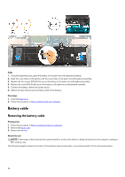
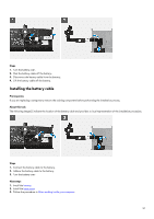
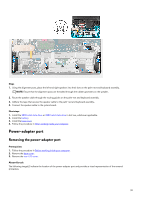
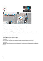
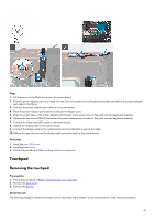
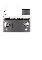
Steps 1. Lift the corner of the Mylar that covers the system board. 2. Slide the power-adapter port at an angle into the slot on the palm-rest and keyboard assembly and adhere the power-adapter port cable to the Mylar. 3. Connect the power-adapter port cable to the system board. 4. Place the power-adapter port bracket on the power-adapter port. 5. Align the screw holes on the power-adapter port bracket to the screw holes on the palm-rest and keyboard assembly. 6. Replace the two screws (M2x4) that secure the power-adapter port bracket to the palm-rest and keyboard assembly. 7. Connect the Alien head LED-cable to the system board. 8. Adhere the display cable to the system board. 9. Connect the display cable to the system board and close the latch to secure the cable. 10. Adhere the tape that secures the display-cable connector latch to the system board. Next steps 1. Install the rear-I/O cover. 2. Install the base cover. 3. Follow the procedure in After working inside your computer. Touchpad Removing the touchpad Prerequisites 1. Follow the procedure in Before working inside your computer. 2. Remove the base cover. 3. Remove the battery. About this task The following image(s) indicate the location of the touchpad and provides a visual representation of the removal procedure. 41
-
 1
1 -
2
-
3
-
4
-
5
-
6
-
7
-
8
-
9
-
10
-
11
-
12
-
13
-
14
-
15
-
16
-
17
-
18
-
19
-
20
-
21
-
22
-
23
-
24
-
25
-
26
-
27
-
28
-
29
-
30
-
31
-
32
-
33
-
34
-
35
-
 36
36 -
 37
37 -
 38
38 -
 39
39 -
 40
40 -
 41
41 -
 42
42 -
 43
43 -
 44
44 -
 45
45 -
 46
46 -
47
-
48
-
49
-
50
-
51
-
52
-
53
-
54
-
55
-
56
-
57
-
58
-
59
-
60
-
61
-
62
-
63
-
64
-
65
-
66
-
67
-
68
-
69
-
70
-
71
-
72
-
73
-
74
-
75
-
76
-
77
-
78
-
79
-
80
-
81
-
82
-
83
-
84
-
85
-
86
 |
 |
