Dell Alienware m15 R7 Service Manual - Page 64
Installing the palm-rest and keyboard assembly
 |
View all Dell Alienware m15 R7 manuals
Add to My Manuals
Save this manual to your list of manuals |
Page 64 highlights
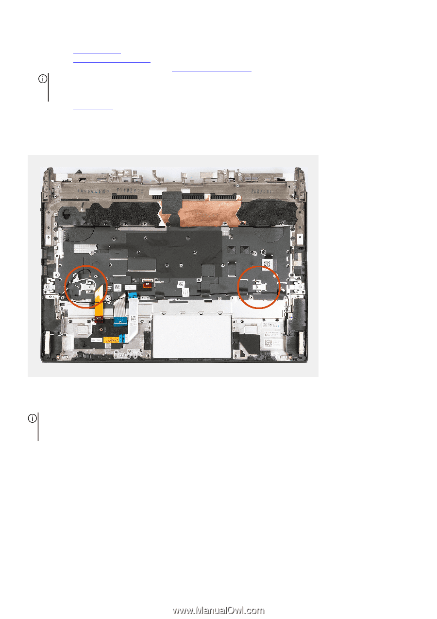
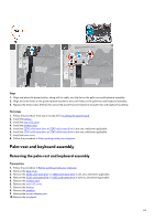
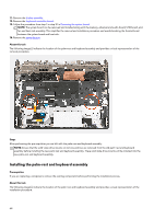
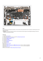
11. Remove the display assembly. 12. Remove the keyboard-controller board. 13. Follow the procedure from step 1 to step 21 in Removing the system board. NOTE: The system board can be removed and installed along with the memory, ethernet and audio board, USB board, and fan and heat sink-assembly. This simplifies the removal and installation procedure and avoids breaking the thermal bond between the system board and heat sink. 14. Remove the power button. About this task The following image(s) indicate the location of the palm-rest and keyboard assembly and provides a visual representation of the removal procedure. Steps After performing the pre-requisites you are left with the palm-rest and keyboard assembly. NOTE: Ensure that the solid-state drive mounts on slot one and two are removed from the old palm-rest and keyboard assembly before installing the new palm-rest and keyboard assembly. These solid-state drive mounts will be installed into the new palm-rest and keyboard assembly. Installing the palm-rest and keyboard assembly Prerequisites If you are replacing a component, remove the existing component before performing the installation process. About this task The following image(s) indicate the location of the palm-rest and keyboard assembly and provides a visual representation of the installation procedure. 64
-
 1
1 -
2
-
3
-
4
-
5
-
6
-
7
-
8
-
9
-
10
-
11
-
12
-
13
-
14
-
15
-
16
-
17
-
18
-
19
-
20
-
21
-
22
-
23
-
24
-
25
-
26
-
27
-
28
-
29
-
30
-
31
-
32
-
33
-
34
-
35
-
36
-
37
-
38
-
39
-
40
-
41
-
42
-
43
-
44
-
45
-
46
-
47
-
48
-
49
-
50
-
51
-
52
-
53
-
54
-
55
-
56
-
57
-
58
-
 59
59 -
 60
60 -
 61
61 -
 62
62 -
 63
63 -
 64
64 -
 65
65 -
 66
66 -
 67
67 -
 68
68 -
 69
69 -
70
-
71
-
72
-
73
-
74
-
75
-
76
-
77
-
78
-
79
-
80
-
81
-
82
-
83
-
84
-
85
-
86
 |
 |