Dell Alienware m15 R7 Service Manual - Page 52
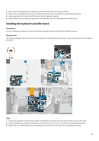
Installing the system board
 |
View all Dell Alienware m15 R7 manuals
Add to My Manuals
Save this manual to your list of manuals |
Page 52 highlights
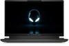
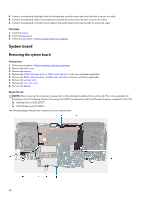
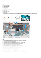
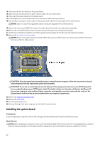
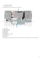
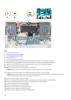
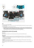
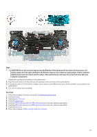
14. Disconnect the left-fan cable from the system board. 15. Open the latch and disconnect the power-button cable from the system board. 16. Disconnect the camera cable from the system board. 17. Lift the Mylar that covers the tapes that secure the camera cable to the system board. 18. Peel the tapes securing the camera cable to the system board and lift the camera cable off the system board. NOTE: Step 16 to step 18 are applicable only for computers shipped with an infrared camera. 19. Remove the seven screws (M2x4) that secure the system board to the palm-rest and keyboard assembly. 20.Remove the screw (M2x2) that secures the system board to the palm-rest and keyboard assembly. 21. Hold firmly on the left and right fans and lift the system-board assembly off the palm-rest and keyboard assembly. 22.Remove the fan and heat-sink assembly. NOTE: Before returning the old system board. Adhere the processor (CPU) sticker over the processor (CPU) chip surface and ensure that it is fully covered . CAUTION: Once the system board assembly has been removed from the computer, follow the instructions in the tech sheet dispatched with the replacement system board assembly. CAUTION: Do not use an alcohol wipe to clean the Element 31 thermal grease from the processor (CPU) chip which is surrounded by the processor (CPU) barrier sheet. The alcohol solution from the wipes will dissolve the Element 31 grease into conductive metal particles. If these conductive metal particles come into contact with the surface of the system board, it will cause the an electrical short when your computer is powered on. 23.Remove the ethernet and audio board. 24.Remove the USB board. 25.Turn the system board over. 26.After performing all the above steps, you are left with the system board. Installing the system board Prerequisites If you are replacing a component, remove the existing component before performing the installation process. About this task NOTE: When installing this component, refer to the techsheet bundled with the service kit. This is only applicable for computers with the following Graphics Processing Unit (GPU) configurations that have Element 31 grease is applied to the CPU. 52
-
 1
1 -
2
-
3
-
4
-
5
-
6
-
7
-
8
-
9
-
10
-
11
-
12
-
13
-
14
-
15
-
16
-
17
-
18
-
19
-
20
-
21
-
22
-
23
-
24
-
25
-
26
-
27
-
28
-
29
-
30
-
31
-
32
-
33
-
34
-
35
-
36
-
37
-
38
-
39
-
40
-
41
-
42
-
43
-
44
-
45
-
46
-
 47
47 -
 48
48 -
 49
49 -
 50
50 -
 51
51 -
 52
52 -
 53
53 -
 54
54 -
 55
55 -
 56
56 -
 57
57 -
58
-
59
-
60
-
61
-
62
-
63
-
64
-
65
-
66
-
67
-
68
-
69
-
70
-
71
-
72
-
73
-
74
-
75
-
76
-
77
-
78
-
79
-
80
-
81
-
82
-
83
-
84
-
85
-
86
 |
 |