Dell Alienware m15 R7 Service Manual - Page 47
Steps, CAUTION: To avoid damaging the display
 |
View all Dell Alienware m15 R7 manuals
Add to My Manuals
Save this manual to your list of manuals |
Page 47 highlights
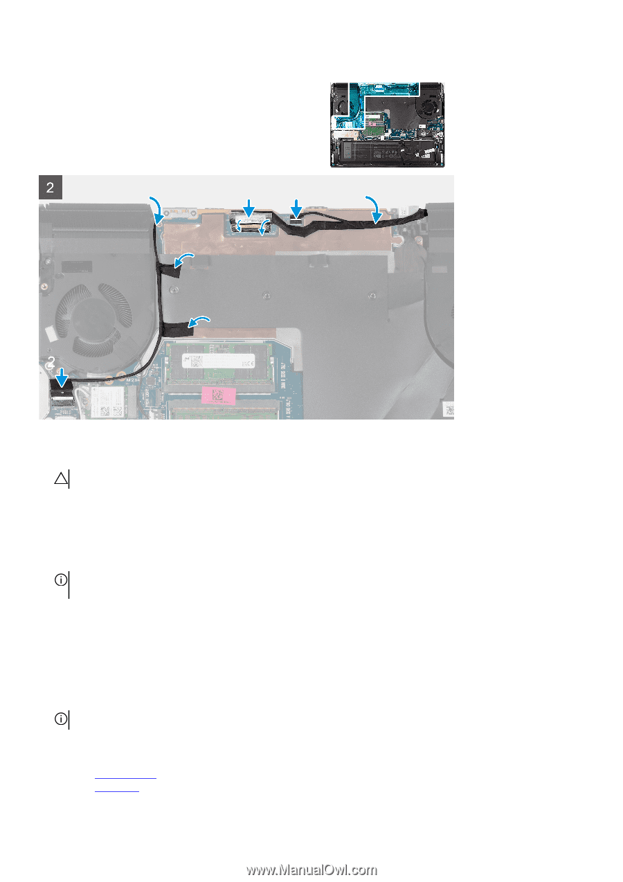
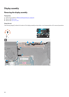
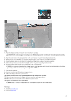
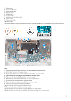
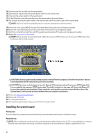
Steps 1. Place the display assembly on the palm-rest and keyboard assembly. CAUTION: To avoid damaging the display, do not slide display assembly over the palm-rest and keyboard assembly. 2. Align the screw holes on the display assembly to the screw holes on the palm-rest and keyboard assembly. 3. Replace the six screws (M2.5x5) that secure the display assembly to the palm-rest and keyboard assembly. 4. Route the display cable and Alien head LED-cable through the routing guides on the display assembly. 5. Adhere the tape that secures the Alien head LED-cable to the palm-rest and keyboard assembly. 6. Route the camera cable through the routing guides on the display assembly. NOTE: For computers shipped with an infrared camera, route the camera cable through the routing guides on the display assembly and then into the opening to the right of the HDMI port. 7. Turn over the computer. 8. Connect the Alien head LED-cable to the system board. 9. Adhere the display cable to the system board. 10. Connect the display cable to the system board and close the latch to secure the cable. 11. Adhere the tape that secures the display-cable connector latch to the system board. 12. Adhere the tapes that secure the camera cable to the system board. 13. Connect the camera cable to the system board. NOTE: Step 11 to step 12 are applicable only for computers shipped with an infrared camera. Next steps 1. Install the rear-I/O cover. 2. Install the base cover. 47
-
 1
1 -
2
-
3
-
4
-
5
-
6
-
7
-
8
-
9
-
10
-
11
-
12
-
13
-
14
-
15
-
16
-
17
-
18
-
19
-
20
-
21
-
22
-
23
-
24
-
25
-
26
-
27
-
28
-
29
-
30
-
31
-
32
-
33
-
34
-
35
-
36
-
37
-
38
-
39
-
40
-
41
-
 42
42 -
 43
43 -
 44
44 -
 45
45 -
 46
46 -
 47
47 -
 48
48 -
 49
49 -
 50
50 -
 51
51 -
 52
52 -
53
-
54
-
55
-
56
-
57
-
58
-
59
-
60
-
61
-
62
-
63
-
64
-
65
-
66
-
67
-
68
-
69
-
70
-
71
-
72
-
73
-
74
-
75
-
76
-
77
-
78
-
79
-
80
-
81
-
82
-
83
-
84
-
85
-
86
 |
 |