Dell Alienware m15 R7 Service Manual - Page 45
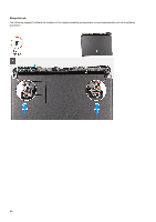
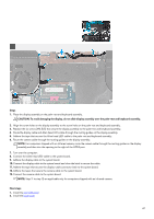
Installing the display assembly, Steps, Prerequisites
 |
View all Dell Alienware m15 R7 manuals
Add to My Manuals
Save this manual to your list of manuals |
Page 45 highlights
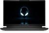
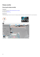
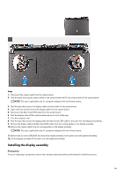
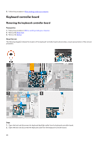
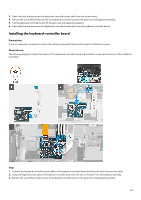
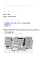
Steps 1. Disconnect the camera cable from the system board. 2. Peel the tapes securing the camera cable to the system board and lift the camera cable off the system board. NOTE: This step is applicable only for computers shipped with an infrared camera. 3. Peel the tape that secures the display-cable connector latch to the system board. 4. Open the latch and disconnect the display cable from the system board. 5. Disconnect the Alien head LED-cable from the system board. 6. Peel the display cable off the system board and move it out of the way. 7. Turn the computer over. 8. Peel the tape that secures the display cable and Alien head LED-cable to the palm-rest and keyboard assembly.. 9. Remove the display cable and Alien head LED-cable from the routing guides on the display assembly. 10. Remove the camera cable from the routing guides on the display assembly. NOTE: This step is applicable only for computers shipped with an infrared camera. 11. Remove the six screws (M2.5x5) that secure the display assembly to the palm-rest and keyboard assembly. 12. Lift the display assembly off the palm-rest and keyboard assembly. Installing the display assembly Prerequisites If you are replacing a component, remove the existing component before performing the installation process. 45
-
 1
1 -
2
-
3
-
4
-
5
-
6
-
7
-
8
-
9
-
10
-
11
-
12
-
13
-
14
-
15
-
16
-
17
-
18
-
19
-
20
-
21
-
22
-
23
-
24
-
25
-
26
-
27
-
28
-
29
-
30
-
31
-
32
-
33
-
34
-
35
-
36
-
37
-
38
-
39
-
 40
40 -
 41
41 -
 42
42 -
 43
43 -
 44
44 -
 45
45 -
 46
46 -
 47
47 -
 48
48 -
 49
49 -
 50
50 -
51
-
52
-
53
-
54
-
55
-
56
-
57
-
58
-
59
-
60
-
61
-
62
-
63
-
64
-
65
-
66
-
67
-
68
-
69
-
70
-
71
-
72
-
73
-
74
-
75
-
76
-
77
-
78
-
79
-
80
-
81
-
82
-
83
-
84
-
85
-
86
 |
 |