Dell MXG610s Fibre Channel Switch Module Installation Guide May 2018 - Page 10
Nonport-side view, Module management options
 |
View all Dell MXG610s manuals
Add to My Manuals
Save this manual to your list of manuals |
Page 10 highlights
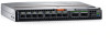
Figure 2. Switch module port-side view 1 SFP+ ports 0, 17-23-trunk group 1 3 Module power and status LED 5 External micro-USB console port 2 QSFP ports 24-27 and 28-31-trunk group 2 4 Module identification LED NOTE: You can group any two to eight ports within a trunk group to form a trunk. Trunking requires an ISL trunking license. Nonport-side view The nonport side of the switch module is not externally visible and is internally plugged into the Dell EMC PowerEdge MX7000 chassis backplane. The switch module seats correctly when the insertion arm is closed. Figure 3. Backplane connectors 1 Backplane connectors Module management options To monitor the fabric topology, port status, physical status, and other information, use the management functions built into the module. Management functions help you analyze switch module performance and accelerate system debugging. The device automatically performs a power-on self-test (POST) each time you turn it on for the first time. A RAS log message generates for any detected startup errors. You can manage the device using any of the management options listed in the following table: 10 Switch module overview
-
 1
1 -
2
-
3
-
4
-
 5
5 -
 6
6 -
 7
7 -
 8
8 -
 9
9 -
 10
10 -
 11
11 -
 12
12 -
 13
13 -
 14
14 -
 15
15 -
16
-
17
-
18
-
19
-
20
-
21
-
22
-
23
-
24
-
25
-
26
-
27
-
28
-
29
-
30
-
31
-
32
-
33
-
34
-
35
-
36
-
37
-
38
-
39
-
40
-
41
-
42
-
43
-
44
-
45
 |
 |
