Dell MXG610s Fibre Channel Switch Module Installation Guide May 2018 - Page 18
Release lever and latch, Insert the SFP+ or QSFP optical transceivers.
 |
View all Dell MXG610s manuals
Add to My Manuals
Save this manual to your list of manuals |
Page 18 highlights
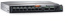
Figure 6. Release lever and latch 1 Backplane connectors 3 Switch module release lever and latch 6 Slide the switch module out of the I/O module bay and set it aside. 2 Switch module top view NOTE: If you do not insert a replacement switch module, to maintain proper airflow and cooling, use a filler blade to fill the empty slot. Do not leave the slot empty. 7 Insert the replacement switch module in the I/O module bay of the blade server chassis. Complete this step within 60 seconds. 8 Insert the SFP+ or QSFP optical transceivers. 9 Reconnect the cables. For more information, see the SFP+ or QSFP optical transceivers documentation. 10 Establish a connection to the blade server management module. 18 Switch module installation overview
-
 1
1 -
2
-
3
-
4
-
5
-
6
-
7
-
8
-
9
-
10
-
11
-
12
-
 13
13 -
 14
14 -
 15
15 -
 16
16 -
 17
17 -
 18
18 -
 19
19 -
 20
20 -
 21
21 -
 22
22 -
 23
23 -
24
-
25
-
26
-
27
-
28
-
29
-
30
-
31
-
32
-
33
-
34
-
35
-
36
-
37
-
38
-
39
-
40
-
41
-
42
-
43
-
44
-
45
 |
 |

Figure 6. Release lever and latch
1
Backplane connectors
2
Switch module top view
3
Switch module release lever and latch
6
Slide the switch module out of the I/O module bay and set it aside.
NOTE:
If you do not insert a replacement switch module, to maintain proper
airflow
and cooling, use a
filler
blade to
fill
the
empty slot. Do not leave the slot empty.
7
Insert the replacement switch module in the I/O module bay of the blade server chassis.
Complete this step within 60 seconds.
8
Insert the SFP+ or QSFP optical transceivers.
9
Reconnect the cables.
For more information, see the SFP+ or QSFP optical transceivers documentation.
10
Establish a connection to the blade server management module.
18
Switch module installation overview